
Chapter 1
The National Airspace System
Communication frequencies are listed in the order in which they would be used during the approach. Frequencies for weather and related facilities are included, where applicable, such as ATIS, ASOS, AWOS, and AFSSs.
The Plan View
The plan view provides a graphical overhead view of the procedure and depicts the routes that guide the pilot from the en route segments to the initial approach fix (IAF). [Figure 1-10] During the initial approach, the aircraft has departed the en route phase of flight and is maneuvering to enter an intermediate or final segment of the instrument approach. An initial approach can be made along prescribed routes within the terminal area, which may be along an arc, radial, course, heading, radar vector, or a combination thereof. Procedure turns and high-altitude teardrop penetrations are initial approach segments. Features of the plan view, including the procedure turn, obstacle elevation, minimum safe altitude (MSA), and procedure track are depicted in Figure 1-11. Terrain is depicted in the plan view portion of all IAPs if the terrain within the plan view exceeds 4,000 feet above the airport elevation, or if within a 6 NM radius of the airport reference point the terrain rises at least 2,000 feet above the airport elevation.
Some AeroNav Products charts contain a reference or distance circle with a specified radius (10 NM is most common). Normally, approach features within the plan view are shown to scale; however, only the data within the reference circle is always drawn to scale.
Concentric dashed circles, or concentric rings around the distance circle, are used when the information necessary to the procedure will not fit to scale within the limits of the plan view area. They serve as a means to systematically arrange this information in its relative position outside and beyond the reference circle. These concentric rings are labeled en route facilities and feeder facilities.
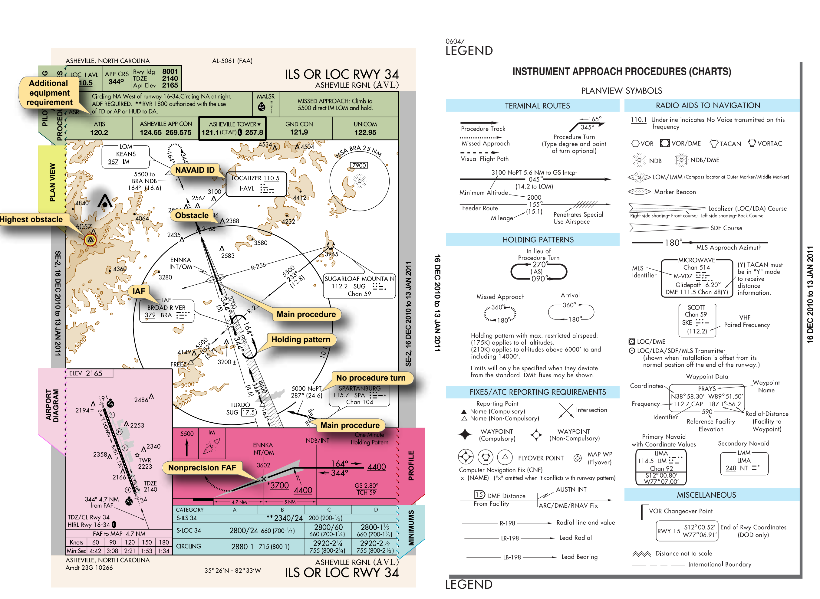
The primary airport depicted in the plan view is drawn with enough detail to show the runway orientation and final approach course alignment. Airports other than the primary approach airport are not normally depicted in the AeroNav Products plan view.
Known spot elevations are indicated on the plan view with a dot in MSL altitude. The largest dot and number combination indicates the highest elevation. An inverted “V” with a dot in the center depicts an obstacle [filled inverted-“V” obstacle symbol with a center dot]. The highest obstacle is indicated with a bolder, larger version of the same symbol. [Figure 1-11]
The MSA circle appears in the plan view, except in approaches for which the Terminal Arrival Area (TAA) format is used or appropriate NAVAIDs (e.g., VOR or NDB) are unavailable. The MSA is provided for emergency purposes only and guarantees 1,000 feet obstruction clearance in the sector indicated with reference to the bearings in the circle. For conventional navigation systems, the MSA is normally based on the primary omnidirectional facility (NAVAID) on which the IAP is predicated. The MSA depiction on the approach chart contains the facility identifier of the NAVAID used to determine the MSA altitudes. For RNAV approaches, the MSA is based on the runway waypoint for straight-in approaches or the airport waypoint for circling approaches. For GPS approaches, the MSA center header is the missed approach waypoint. The MSL altitudes appear in boxes within the circle, which is typically a 25 NM radius unless otherwise indicated. The MSA circle header refers to the letter identifier of the NAVAID or waypoint that describes the center of the circle.
NAVAIDs necessary for the completion of the instrument procedure include the facility name, letter identifier, and Morse code sequence. They may also furnish the frequency, Morse code, and channel. A heavy-lined NAVAID box depicts the primary NAVAID used for the approach. An “I” in front of the NAVAID identifier (in Figure 1-11, “I-AVL”) listed in the NAVAID box indicates a localizer. The requirement for an ADF, DME, or RADAR in the approach is noted in the plan view.
Intersections, fixes, radials, and course lines describe route and approach sequencing information. The main procedure or final approach course is a thick, solid line [thick solid line]. A DME arc, which is part of the main procedure course, is also represented as a thick, solid line [thick solid DME-arc line]. A feeder route is depicted with a medium line [medium feeder-route line] and provides heading, altitude, and distance information. (All three components must be designated on the chart to provide a navigable course.) Radials, such as lead radials, are shown by thin lines [thin radial line]. The missed approach track is drawn using a thin, hash marked line with a directional arrow [thin hash-marked line with directional arrow]. A visual flightpath segment appears as a thick dashed line with a directional arrow [thick dashed visual-flightpath line with directional arrow]. IAFs are charted IAF when associated with a NAVAID or when freestanding.
The missed approach holding pattern track is represented with a thin, dashed line. When collocated, the missed approach holding pattern and procedure turn holding pattern are indicated as a solid, black line. Arrival holding patterns are depicted as thin, solid lines.
Terminal Arrival Area (TAA)
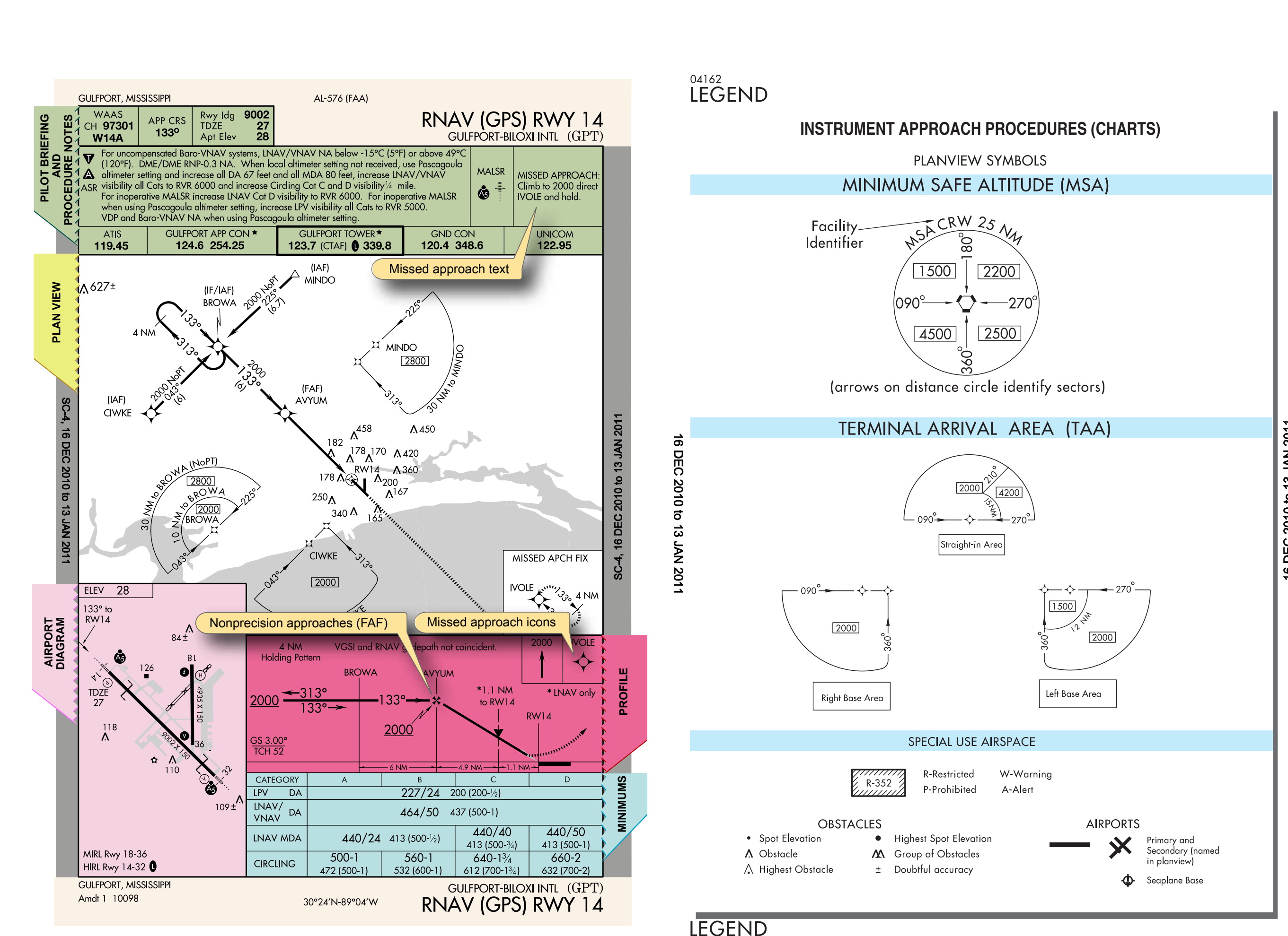
The design objective of the TAA procedure is to provide a transition method for arriving aircraft with GPS/RNAV equipment. TAAs also eliminate or reduce the need for feeder routes, departure extensions, and procedure turns or course reversal. The TAA is controlled airspace established in conjunction with the standard or modified RNAV approach configurations.
The standard TAA has three areas: straight-in, left base, and right base. The arc boundaries of the three areas of the TAA are published portions of the approach and allow aircraft to transition from the en route structure direct to the nearest IAF. When crossing the boundary of each of these areas or when released by ATC within the area, the pilot is expected to proceed direct to the appropriate waypoint IAF for the approach area being flown. A pilot has the option in all areas of proceeding directly to the holding pattern.
The TAA has a “T” structure that normally provides a No Procedure Turn (NoPT) for aircraft using the approach. [Figure 1-12] The TAA provides the pilot and air traffic controller with an efficient method for routing traffic from the en route to the terminal structure. The basic “T” contained in the TAA normally aligns the procedure on runway centerline with the missed approach point (MAP) located at the threshold, the FAF 5 NM from the threshold, and the intermediate fix (IF) 5 NM from the FAF.
In order to accommodate descent from a high en route altitude to the initial segment altitude, a hold in lieu of a procedure turn provides the aircraft with an extended distance for the necessary descent gradient. The holding pattern constructed for this purpose is always established on the center IAF waypoint. Other modifications may be required for parallel runways or special operational requirements. When published, the RNAV chart depicts the TAA through the use of icons representing each TAA associated with the RNAV procedure. These icons are depicted in the plan view of the approach, generally arranged on the chart in accordance with their position relative to the aircraft’s arrival from the en route structure.
Course Reversal Elements in Plan View and Profile View
Course reversals included in an IAP are depicted in one of three different ways: a 45°/180° procedure turn, a holding pattern in lieu of procedure turn, or a teardrop procedure. The maneuvers are required when it is necessary to reverse direction to establish the aircraft inbound on an intermediate or final approach course. Components of the required procedure are depicted in the plan view and the profile view. The maneuver must be completed within the distance and at the minimum altitude specified in the profile view. Pilots should coordinate with the appropriate ATC facility relating to course reversal during the IAP.