
Chapter 11
Emergency Operations
Operating on the Main Battery
While en route to the airport of intended landing, reduce the electrical load as much as practical. Turn off all unnecessary electrical items, such as duplicate radios, non-essential lighting, etc. If unable to turn off radios, lights, etc., manually, consider pulling circuit breakers to isolate those pieces of equipment from the electrical system. Maximum time of useful voltage may be between 30 and 40 minutes and is influenced by many factors, that degrade the useful time.
Loss of Alternator/Generator for Electronic Flight Instrumentation
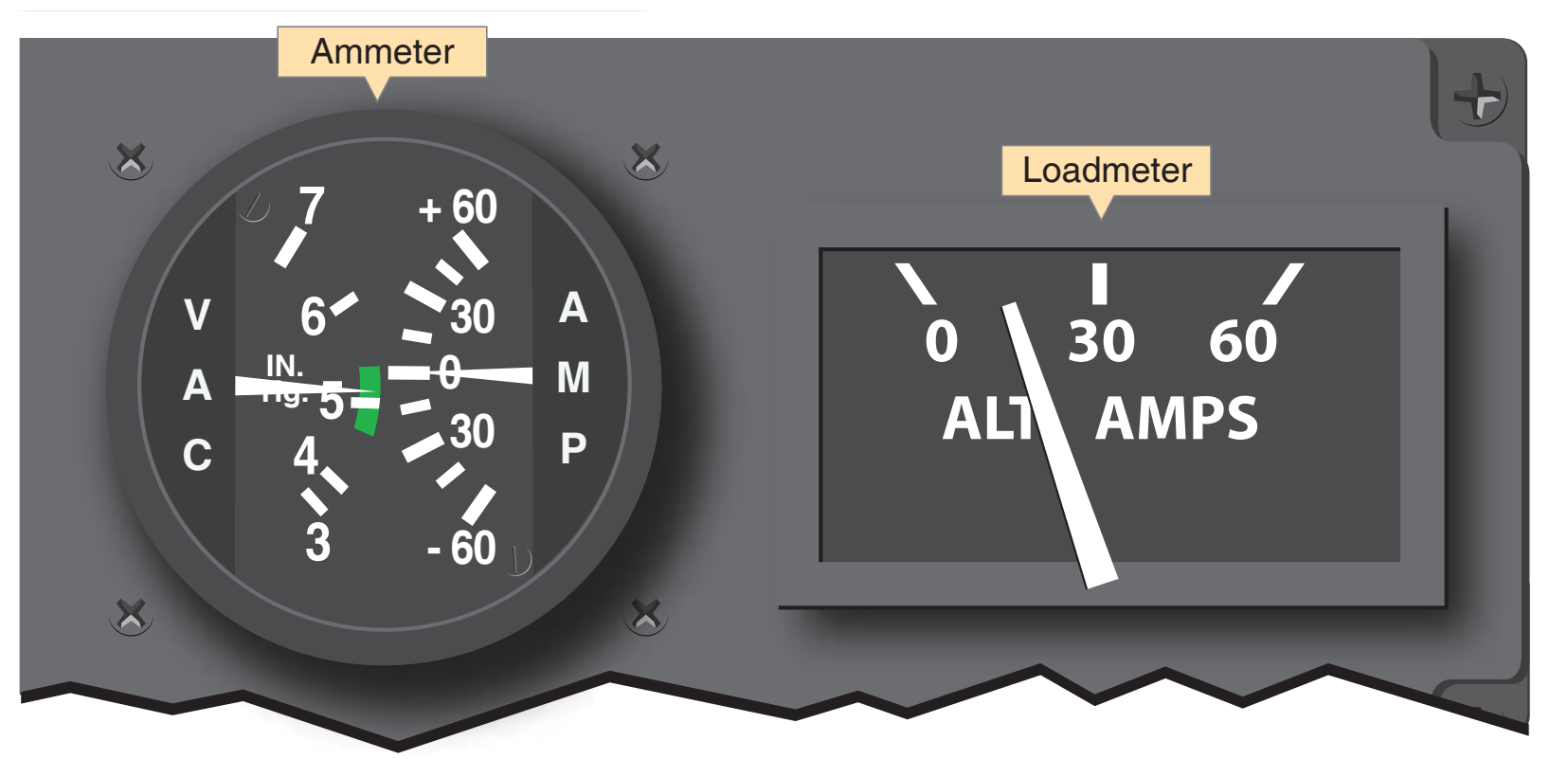
With the increase in electrical components being installed in modern technically advanced aircraft, the power supply and the charging system need increased attention and understanding. Traditional round dial aircraft do not rely as heavily on electrical power for the primary six-pack instrumentation. Modern EFDs utilize the electrical system to power the Attitude Heading Reference System (AHRS), air data computer (ADC), engine indicating system (EIS), etc. A loss of an alternator or generator was considered an abnormality in traditionally-equipped aircraft; however, a failure of this magnitude is considered an emergency in technically advanced aircraft.
Due to the increased demand for electrical power, it is necessary for manufacturers to install a standby battery in conjunction with the primary battery. The standby battery is held in reserve and kept charged in case of a failure of the charging system and a subsequent exhaustion of the main battery. The standby battery is brought online when the main battery voltage is depleted to a specific value, approximately 19 volts. Generally, the standby battery switch must be in the ARM position for this to occur but pilots should refer to the aircraft flight manual (AFM) for specifics on an aircraft’s electrical system. The standby battery powers the essential bus and allows the PFD to be utilized.
The essential bus usually powers the following components:
- AHRS (Attitude and Heading Reference System)
- ADC (Air Data Computer)
- PFD (Primary Flight Display)
- Navigation Radio #1
- Communication Radio #1
- Standby Indicator Light
Techniques for Electrical Usage
Standby Battery
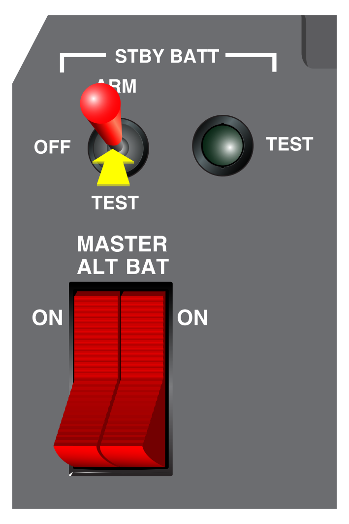
One technique for conserving the main battery charge is to fly the aircraft to the airport of intended landing while using the standby battery. A two-position battery master/ alternator rocker switch is installed on most aircraft with EFDs, which can be utilized to isolate the main battery from the electrical system. By switching the MASTER side off, the battery is taken offline and the standby battery comes online to power the essential bus. However, the standby battery switch must be in the ARM position for this to occur. [Figure 11-6] Utilization of the standby battery first reserves the main battery for use when approaching to land. With this technique, electrical power may be available for the use of flaps, gear, lights, etc. Do not rely on any power to be available after the standby battery has exhausted itself. Once the charging system has failed, flight with a powered electrical system is not guaranteed.
Operating on the Main Battery
While en route to the airport of intended landing, reduce the electrical load as much as practical. Turn off all unnecessary electrical items, such as duplicate radios, non-essential lighting, etc. If unable to turn off radios, lights, etc., manually, consider pulling circuit breakers to isolate those pieces of equipment from the electrical system. Keep in mind that once the standby battery has exhausted its charge, the flight deck may become very dark depending on what time of day the failure occurs. The priority during this emergency situation is landing the aircraft as soon as possible without jeopardizing safety.
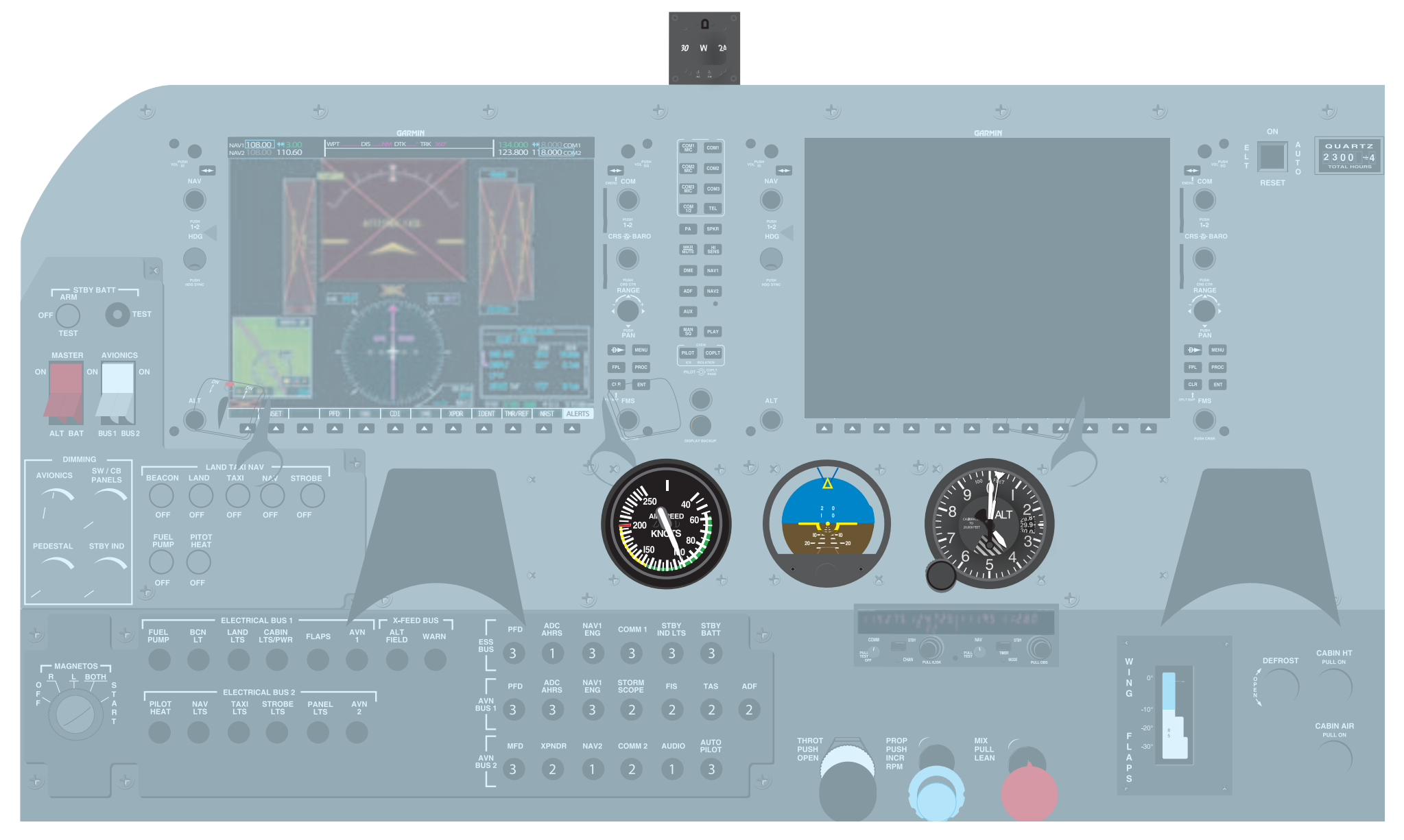
A standby attitude indicator, altimeter, airspeed indicator (ASI) and magnetic compass are installed in each aircraft for use when the PFD instrumentation is unavailable. [Figure 11-7] These would be the only instruments left available to the pilot. Navigation would be limited to pilotage and dead reckoning unless a hand-held transceiver with a global positioning system (GPS)/navigation function is onboard.
Once an alternator failure has been detected, the pilot must reduce the electrical load on the battery and land as soon as practical. Depending upon the electrical load and condition of the battery, there may be sufficient power available for 45 minutes of flight—or for only a matter of minutes. Pilots should also know which systems on the aircraft are electric and those that continue to operate without electrical power. Pilots can attempt to troubleshoot alternator failure by following the established alternator failure procedure published in the POH/AFM. If the alternator cannot be reset, advise ATC of the situation and inform them of the impending electrical failure.
Analog Instrument Failure
A warning indicator, or an inconsistency between indications on the attitude indicator and the supporting performance instruments, usually identifies system or instrument failure. Aircraft control must be maintained while identifying the failed component(s). Expedite the cross-check and include all flight instruments. The problem may be individual instrument failure or a system failure affecting multiple instruments.
One method of identification involves an immediate comparison of the attitude indicator with the rate-of-turn indicator and vertical speed indicator (VSI). Along with providing pitch-and-bank information, this technique compares the static system with the suction or pressure system and the electrical system. Identify the failed component(s) and use the remaining functional instruments to maintain aircraft control.