
Chapter 2
The Air Traffic Control System
The last clearance received supersedes all previous clearances. For example, if the DP says “Climb and maintain 2,000 feet, expect higher in 6 miles,” but upon contacting the departure controller a new clearance is received: “Climb and maintain 8,000 feet,” the 2,000 feet restriction has been canceled. This rule applies in both terminal and Center airspace.
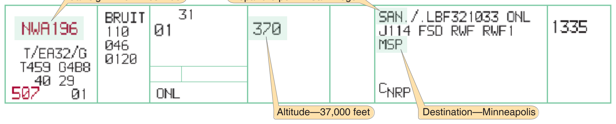
When reporting “ready to copy” an IFR clearance before the strip has been received from the Center computer, pilots are advised “clearance on request.” The controller initiates contact when it has been received. This time can be used for taxi and pre-takeoff checks.
The local controller is responsible for operations in the Class D airspace and on the active runways. At some towers, designated as IFR towers, the local controller has vectoring authority. At visual flight rules (VFR) towers, the local controller accepts inbound IFR flights from the terminal radar facility and cannot provide vectors. The local controller also coordinates flights in the local area with radar controllers. Although Class D airspace normally extends 2,500 feet above field elevation, towers frequently release the top 500 feet to the radar controllers to facilitate overflights. Accordingly, when a flight is vectored over an airport at an altitude that appears to enter the tower controller’s airspace, there is no need to contact the tower controller—all coordination is handled by ATC.
The departure radar controller may be in the same building as the control tower, but it is more likely that the departure radar position is remotely located. The tower controller will not issue a takeoff clearance until the departure controller issues a release.
Terminal Radar Approach Control (TRACON)
TRACONs are considered terminal facilities because they provide the link between the departure airport and the en route structure of the NAS. Terminal airspace normally extends 30 nautical miles (NM) from the facility with a vertical extent of 10,000 feet; however, dimensions vary widely. Class B and Class C airspace dimensions are provided on aeronautical charts. At terminal radar facilities, the airspace is divided into sectors, each with one or more controllers, and each sector is assigned a discrete radio frequency. All terminal facilities are approach controls and should be addressed as “Approach” except when directed to do otherwise (e.g., “Contact departure on 120.4.”).
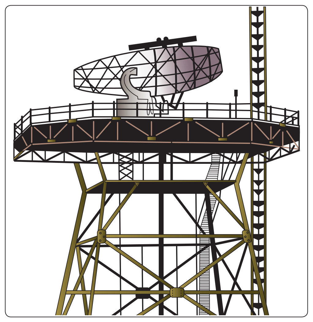
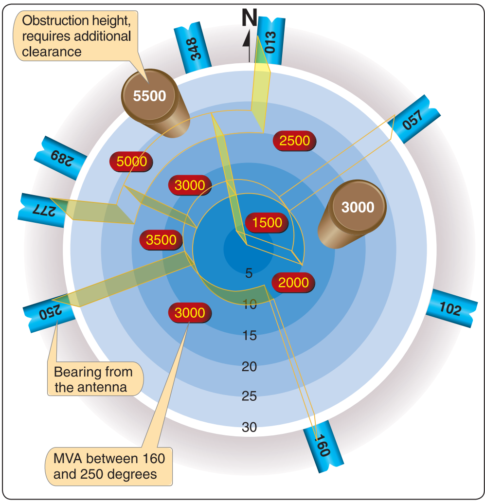
Terminal radar antennas are located on or adjacent to the airport. Figure 2-7 shows a typical configuration. Terminal controllers can assign altitudes lower than published procedural altitudes called minimum vectoring altitudes (MVAs). These altitudes are not published or accessible to pilots, but are displayed at the controller’s position. [Figure 2-8] However, when pilots are assigned an altitude that seems to be too low, they should query the controller before descending.
When a pilot accepts a clearance and reports ready for takeoff, a controller in the tower contacts the TRACON for a release.
An aircraft is not cleared for takeoff until the departure controller can fit the flight into the departure flow. A pilot may have to hold for release. When takeoff clearance is received, the departure controller is aware of the flight and is waiting for a call. All of the information the controller needs is on the departure strip or the computer screen; there is no need to repeat any portion of the clearance to that controller. Simply establish contact with the facility when instructed to do so by the tower controller. The terminal facility computer picks up the transponder and initiates tracking as soon as it detects the assigned code. For this reason, the transponder should remain on standby until takeoff clearance has been received.
The aircraft appears on the controller’s radar display as a target with an associated data block that moves as the aircraft moves through the airspace. The data block includes aircraft identification, aircraft type, altitude, and airspeed.
A TRACON controller uses Airport Surveillance Radar (ASR) to detect primary targets and Automated Radar Terminal Systems (ARTS) to receive transponder signals; the two are combined on the controller’s scope. [Figure 2-9]
At facilities with ASR-3 equipment, radar returns from precipitation are not displayed as varying levels of intensity, and controllers must rely on pilot reports and experience to provide weather avoidance information. With ASR-9 equipment, the controller can select up to six levels of intensity. Light precipitation does not require avoidance tactics but precipitation levels of moderate, heavy, or extreme should cause pilots to plan accordingly. Along with precipitation, the pilot must additionally consider the temperature, which if between –20° and +5 °C causes icing even during light precipitation. The returns from higher levels of intensity may obscure aircraft data blocks, and controllers may select the higher levels only on pilot request. When uncertainty exists about the weather ahead, ask the controller if the facility can display intensity levels—pilots of small aircraft should avoid intensity levels 3 or higher.
Tower En Route Control (TEC)
At many locations, instrument flights can be conducted entirely in terminal airspace. These tower en route control (TEC) routes are generally for aircraft operating below 10,000 feet, and they can be found in the A/FD. Pilots desiring to use TEC should include that designation in the remarks section of the flight plan.
Pilots are not limited to the major airports at the city pairs listed in the A/FD. For example, a tower en route flight from an airport in New York (NYC) airspace could terminate at any airport within approximately 30 miles of Bradley International (BDL) airspace, such as Hartford (HFD). [Figure 2-10]
A valuable service provided by the automated radar equipment at terminal radar facilities is the Minimum Safe Altitude Warnings (MSAW). This equipment predicts an aircraft’s position in 2 minutes based on present path of flight—the controller issues a safety alert if the projected path encounters terrain or an obstruction. An unusually rapid descent rate on a nonprecision approach can trigger such an alert.