
Chapter 2
The Air Traffic Control System
ARTCC facilities are responsible for maintaining separation between IFR flights in the en route structure. Center radars (Air Route Surveillance Radar (ARSR)) acquire and track transponder returns using the same basic technology as terminal radars. [Figure 2-11]
Earlier Center radars display weather as an area of slashes (light precipitation) and Hs (moderate rainfall), as illustrated in Figure 2-12. Because the controller cannot detect higher levels of precipitation, pilots should be wary of areas showing moderate rainfall. Newer radar displays show weather as three levels of blue. Controllers can select the level of weather to be displayed. Weather displays of higher levels of intensity can make it difficult for controllers to see aircraft data blocks, so pilots should not expect ATC to keep weather displayed continuously.
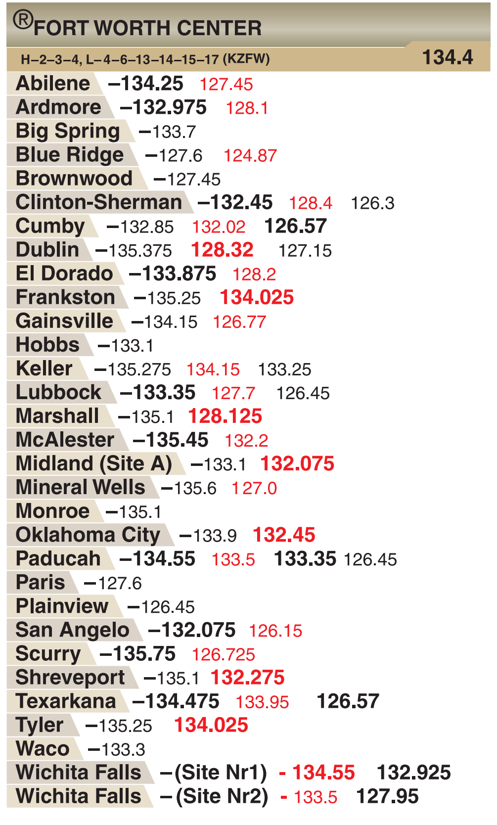
Center airspace is divided into sectors in the same manner as terminal airspace; additionally, most Center airspace is divided by altitudes into high and low sectors. Each sector has a dedicated team of controllers and a selection of radio frequencies because each Center has a network of remote transmitter/receiver sites. All Center frequencies can be found in the back of the A/FD in the format shown in Figure 2-13; they are also found on en route charts.
Each ARTCC’s area of responsibility covers several states; when flying from the vicinity of one remote communication site toward another, expect to hear the same controller on different frequencies.
Center Approach/Departure Control
The majority of airports with instrument approaches do not lie within terminal radar airspace and, when operating to or from these airports, pilots communicate directly with the Center controller. Departing from a tower-controlled airport, the tower controller provides instructions for contacting the appropriate Center controller. When departing an airport without an operating control tower, the clearance includes instructions such as “Upon entering controlled airspace, contact Houston Center on 126.5.” Pilots are responsible for terrain clearance until reaching the controller’s MVA. Simply hearing “Radar contact” does not relieve a pilot of this responsibility.
If obstacles in the departure path require a steeper-than-standard climb gradient (200 feet per nautical mile (FPNM)), then the controller advises the pilot. However, it is the pilot’s responsibility to check the departure airport listing in the A/FD to determine if there are trees or wires in the departure path. When in doubt, ask the controller for the required climb gradient.
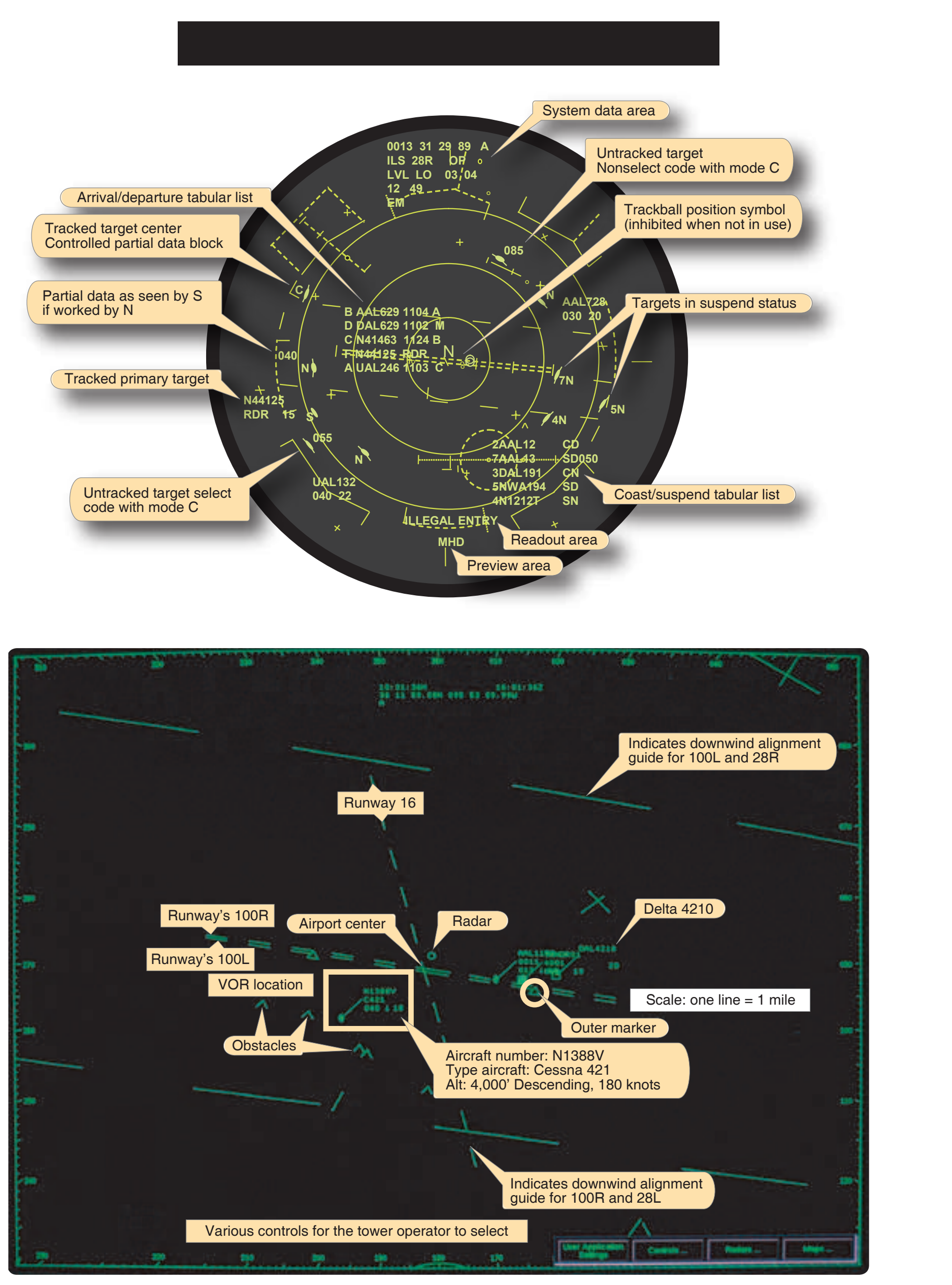
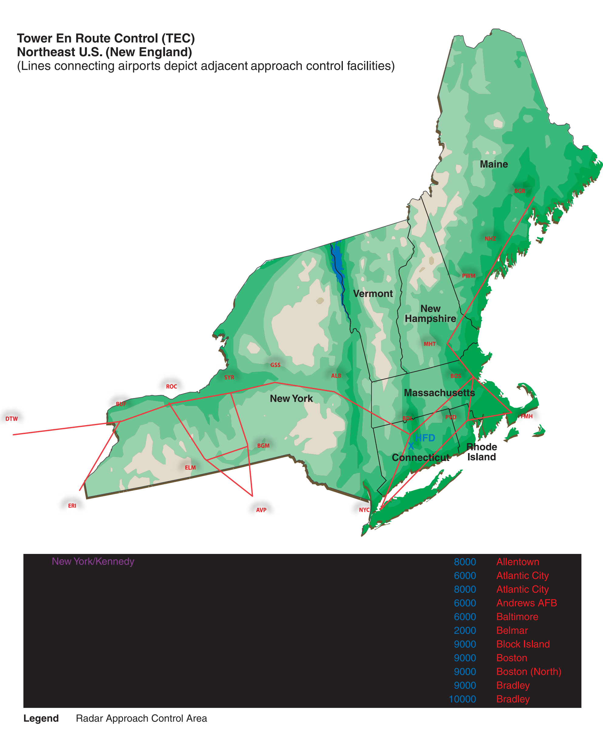
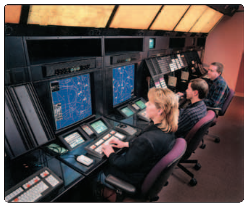
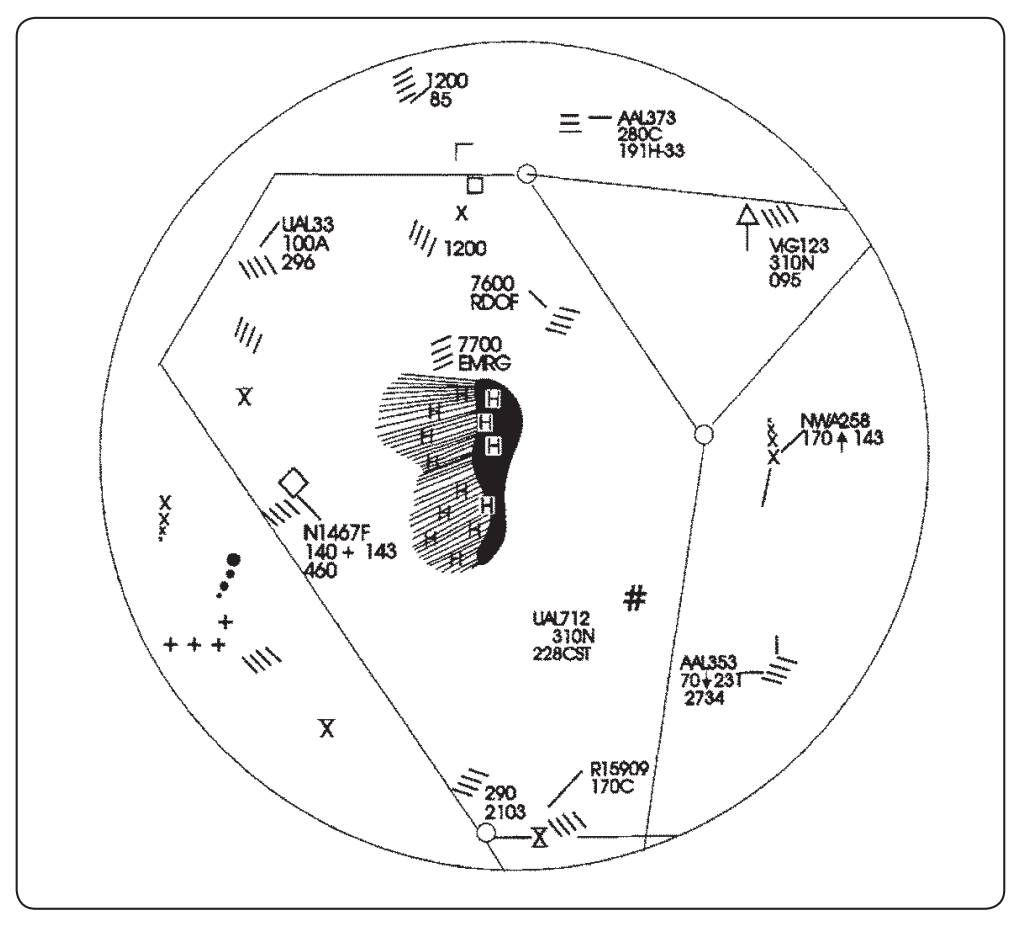
A common clearance in these situations is “When able, proceed direct to the Astoria VOR…” The words “when able” mean to proceed to the waypoint, intersection, or NAVAID when the pilot is able to navigate directly to that point using onboard available systems providing proper guidance, usable signal, etc. If provided such guidance while flying VFR, the pilot remains responsible for terrain and obstacle clearance. Using the standard climb gradient, an aircraft is 2 miles from the departure end of the runway before it is safe to turn (400 feet above ground level (AGL)). When a Center controller issues a heading, a direct route, or says “direct when able,” the controller becomes responsible for terrain and obstruction clearance.
Another common Center clearance is “Leaving (altitude) fly (heading) or proceed direct when able.” This keeps the terrain/obstruction clearance responsibility in the flight deck until above the minimum IFR altitude. A controller cannot issue an IFR clearance until an aircraft is above the minimum IFR altitude unless it is able to climb in VFR conditions.
On a Center controller’s scope, 1 NM is about ⁄ of an inch. When a Center controller is providing Approach/Departure control services at an airport many miles from the radar antenna, estimating headings and distances is very difficult. Controllers providing vectors to final must set the range on their scopes to not more than 125 NM to provide the greatest possible accuracy for intercept headings. Accordingly, at locations more distant from a Center radar antenna, pilots should expect a minimum of vectoring.
ATC Inflight Weather Avoidance Assistance
ATC Radar Weather Displays
ATC radar systems are able to display areas of precipitation by sending out a beam of radio energy that is reflected back to the radar antenna when it strikes an object or moisture, which may be in the form of rain drops, hail, or snow. The larger the object, or the denser its reflective surface, the stronger the return. Radar weather processors indicate the intensity of reflective returns in terms of decibels with respect to the radar reflectively factor (dBZ).
ATC systems cannot detect the presence or absence of clouds. ATC radar systems can often determine the intensity of a precipitation area, but the specific character of that area (snow, rain, hail, VIRGA, etc.) cannot be determined. For this reason, ATC refers to all weather areas displayed on ATC radar scopes as “precipitation.”
All ATC facilities using radar weather processors with the ability to determine precipitation intensity describes the intensity to pilots as: