Chapter 5
Flight Instruments
The dial of these instruments is marked “2 MIN TURN.” Some turn-and-slip indicators used in faster aircraft are marked “4 MIN TURN.” In either instrument, a standard rate turn is being made whenever the needle aligns with a doghouse. A standard rate turn is 3° per second. In a 2 minute instrument, if the needle is one needle width either side of the center alignment mark, the turn is 3° per second and the turn takes 2 minutes to execute a 360° turn. In a 4 minute instrument, the same turn takes two widths deflection of the needle to achieve 3° per second.
Turn Coordinator
The major limitation of the older turn-and-slip indicator is that it senses rotation only about the vertical axis of the aircraft. It tells nothing of the rotation around the longitudinal axis, which in normal flight occurs before the aircraft begins to turn.
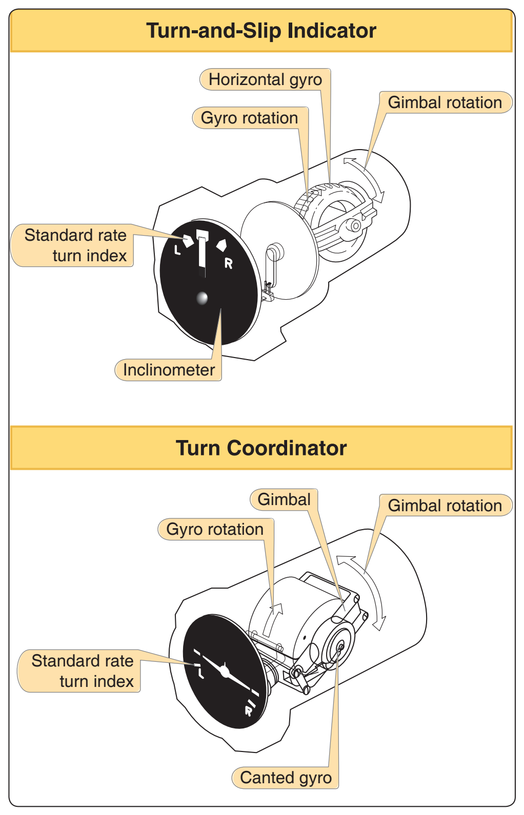
A turn coordinator operates on precession, the same as the turn indicator, but its gimbals frame is angled upward about 30° from the longitudinal axis of the aircraft. [Figure 5-34] This allows it to sense both roll and yaw. Therefore during a turn, the indicator first shows the rate of banking and once stabilized, the turn rate. Some turn coordinator gyros are dual-powered and can be driven by either air or electricity.
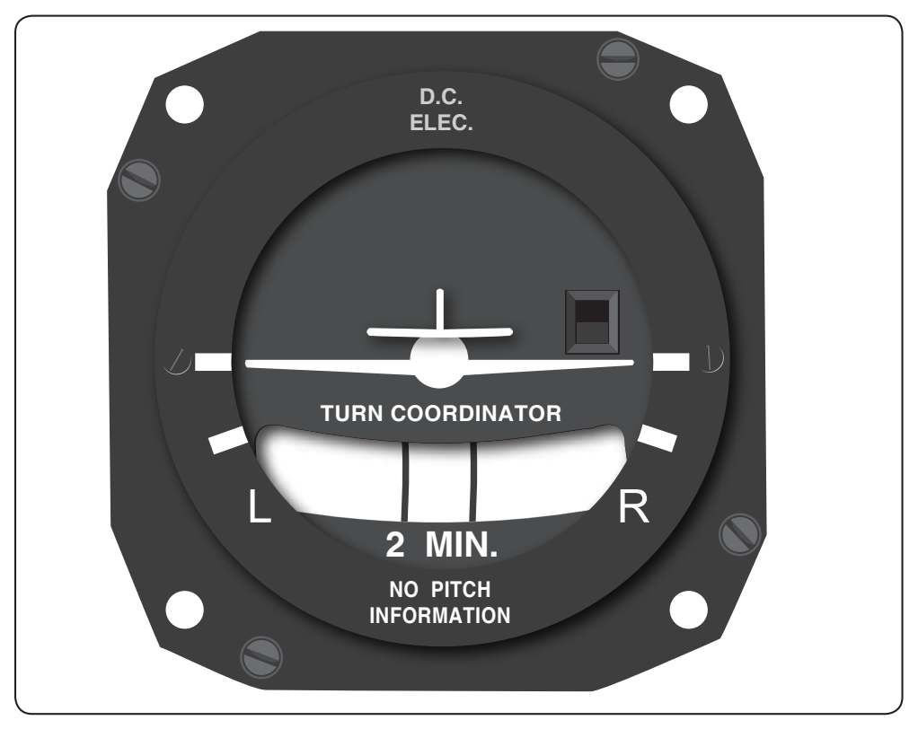
Rather than using a needle as an indicator, the gimbal moves a dial that is the rear view of a symbolic aircraft. The bezel of the instrument is marked to show wings-level flight and bank angles for a standard rate turn. [Figure 5-35]
The inclinometer, similar to the one in a turn-and-slip indicator, is called a coordination ball, which shows the relationship between the bank angle and the rate of yaw. The turn is coordinated when the ball is in the center, between the marks. The aircraft is skidding when the ball rolls toward the outside of the turn and is slipping when it moves toward the inside of the turn. A turn coordinator does not sense pitch. This is indicated on some instruments by placing the words “NO PITCH INFORMATION” on the dial.
Flight Support Systems
Attitude and Heading Reference System (AHRS)
As aircraft displays have transitioned to new technology, the sensors that feed them have also undergone significant change. Traditional gyroscopic flight instruments have been replaced by Attitude and Heading Reference Systems (AHRS) improving reliability and thereby reducing cost and maintenance.
The function of an AHRS is the same as gyroscopic systems; that is, to determine which way is level and which way is north. By knowing the initial heading the AHRS can determine both the attitude and magnetic heading of the aircraft.
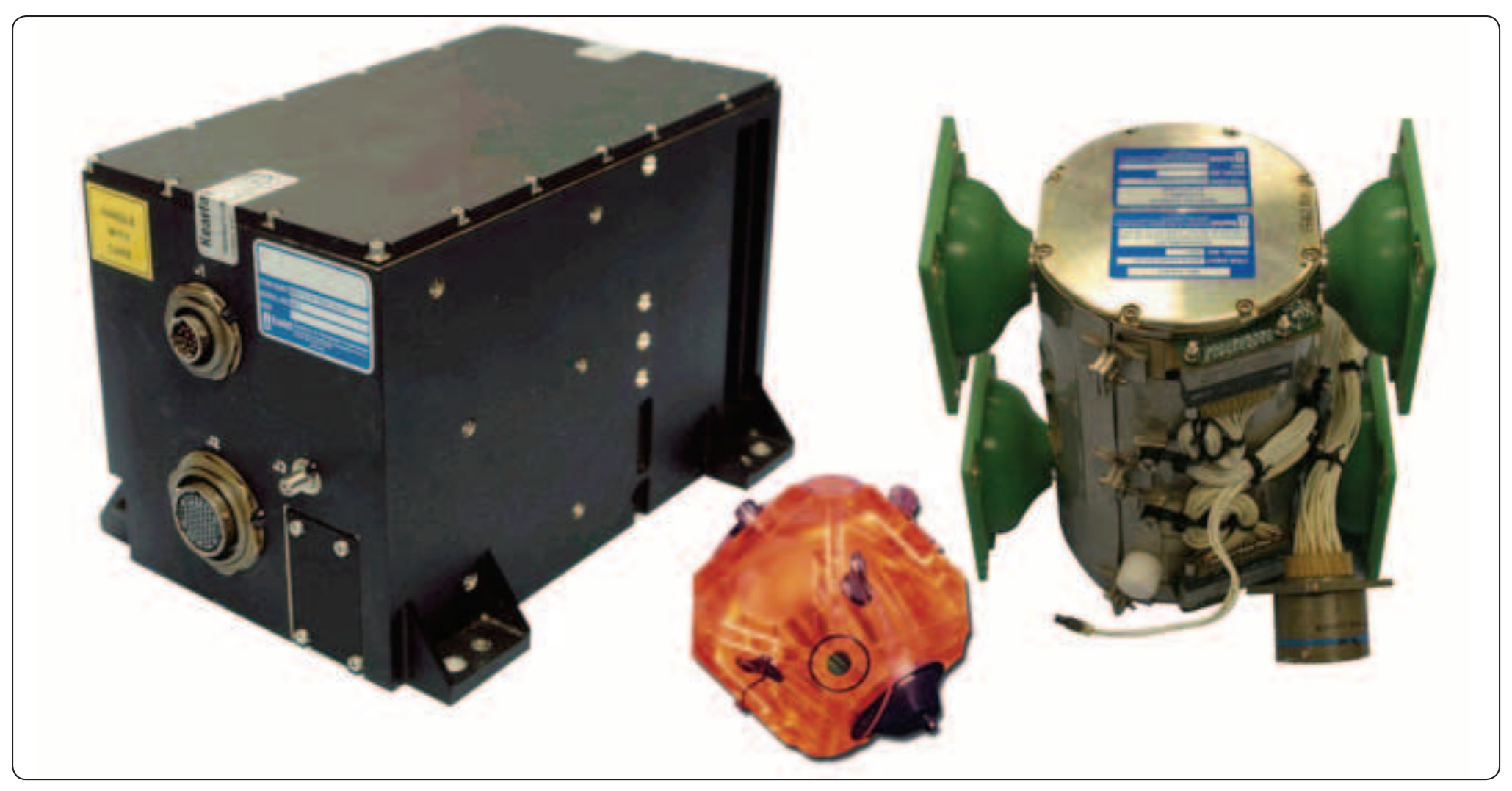
The genesis of this system was initiated by the development of the ring-LASAR gyroscope developed by Kearfott located in Little Falls, New Jersey. [Figure 5-36] Their development of the Ring-LASAR gyroscope in the 1960s/1970s was in support of Department of Defense (DOD) programs to include cruise missile technology. With the precision of these gyroscopes, it became readily apparent that they could be leveraged for multiple tasks and functions. Gyroscopic miniaturization has become so common that solid-state gyroscopes are found in products from robotics to toys.
Because the AHRS system replaces separate gyroscopes, such as those associated with an attitude indicator, magnetic heading indicator and turn indicator these individual systems are no longer needed. As with many systems today, AHRS itself had matured with time. Early AHRS systems used expensive inertial sensors and flux valves. However, today the AHRS for aviation and general aviation in particular are small solid-state systems integrating a variety of technology such as low cost inertial sensors, rate gyros, and magnetometers, and have capability for satellite signal reception.
Air Data Computer (ADC)
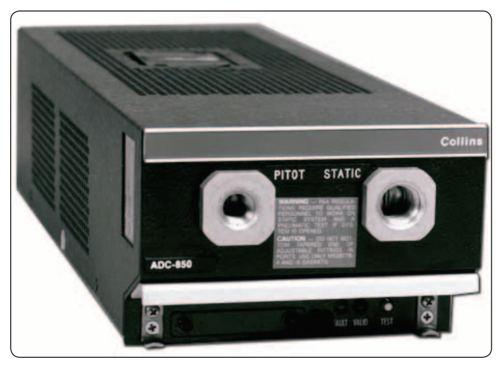
An Air Data Computer (ADC) [Figure 5-37] is an aircraft computer that receives and processes pitot pressure, static pressure, and temperature to calculate very precise altitude, IAS, TAS, and air temperature. The ADC outputs this information in a digital format that can be used by a variety of aircraft systems including an EFIS. Modern ADCs are small solid-state units. Increasingly, aircraft systems such as autopilots, pressurization, and FMS utilize ADC information for normal operations.