Chapter 5
Flight Instruments
Venturi Tube Systems
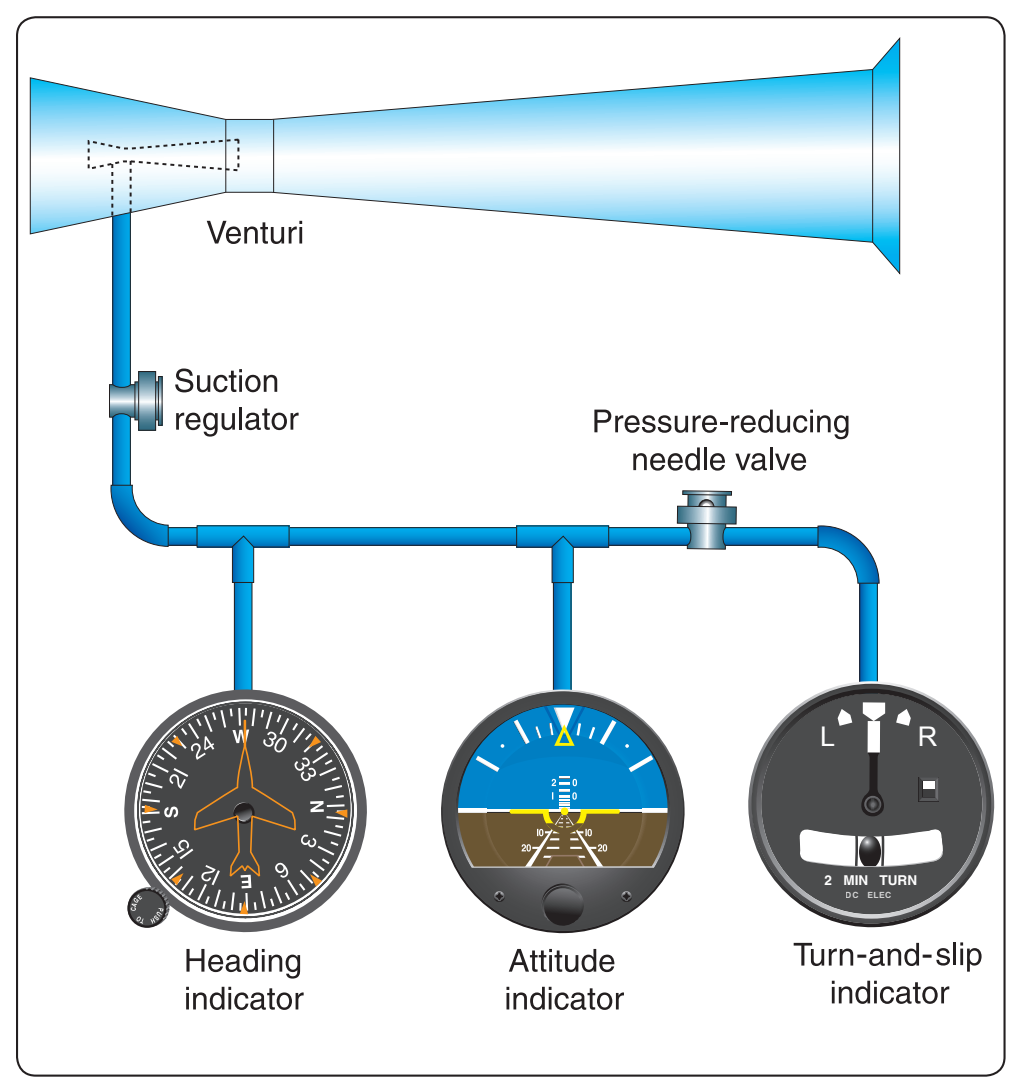
Aircraft that do not have a pneumatic pump to evacuate the instrument case can use venturi tubes mounted on the outside of the aircraft, similar to the system shown in Figure 5-27. Air flowing through the venturi tube speeds up in the narrowest part and, according to Bernoulli’s principle, the pressure drops. This location is connected to the instrument case by a piece of tubing. The two attitude instruments operate on approximately 4 "Hg of suction; the turn-and-slip indicator needs only 2 "Hg, so a pressure-reducing needle valve is used to decrease the suction. Air flows into the instruments through filters built into the instrument cases. In this system, ice can clog the venturi tube and stop the instruments when they are most needed.
Vacuum Pump Systems
Wet-Type Vacuum Pump
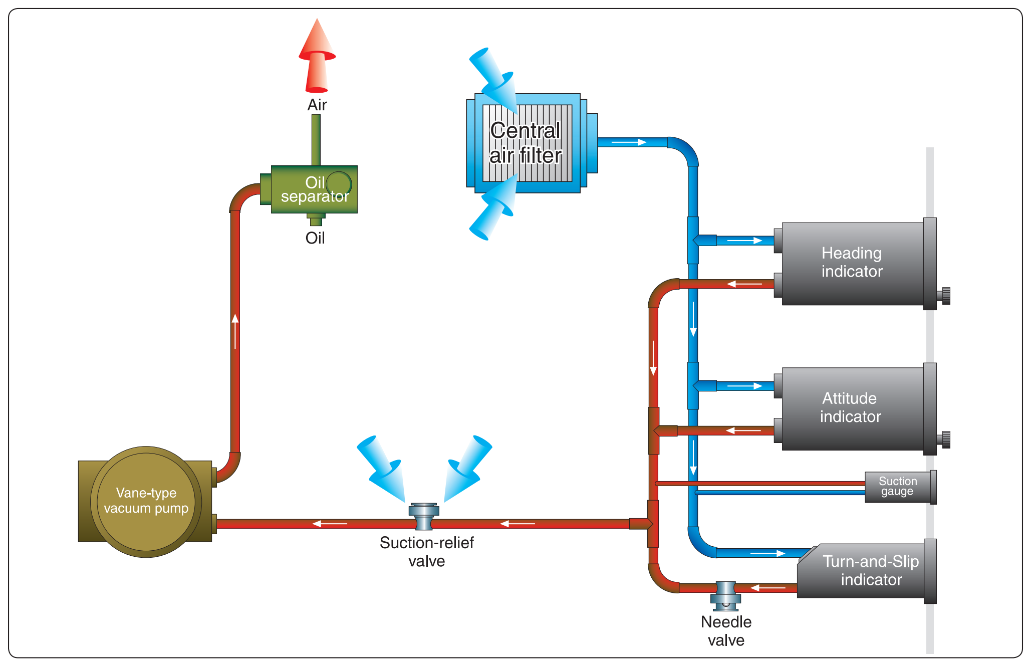
Steel-vane air pumps have been used for many years to evacuate the instrument cases. The vanes in these pumps are lubricated by a small amount of engine oil metered into the pump and discharged with the air. In some aircraft the discharge air is used to inflate rubber deicer boots on the wing and empennage leading edges. To keep the oil from deteriorating the rubber boots, it must be removed with an oil separator like the one in Figure 5-28.
The vacuum pump moves a greater volume of air than is needed to supply the instruments with the suction needed, so a suction-relief valve is installed in the inlet side of the pump. This spring-loaded valve draws in just enough air to maintain the required low pressure inside the instruments, as is shown on the suction gauge in the instrument panel. Filtered air enters the instrument cases from a central air filter. As long as aircraft fly at relatively low altitudes, enough air is drawn into the instrument cases to spin the gyros at a sufficiently high speed.
Dry Air Vacuum Pump
As flight altitudes increase, the air is less dense and more air must be forced through the instruments. Air pumps that do not mix oil with the discharge air are used in high flying aircraft. Steel vanes sliding in a steel housing need to be lubricated, but vanes made of a special formulation of carbon sliding inside carbon housing provide their own lubrication in a microscopic amount as they wear.
Pressure Indicating Systems
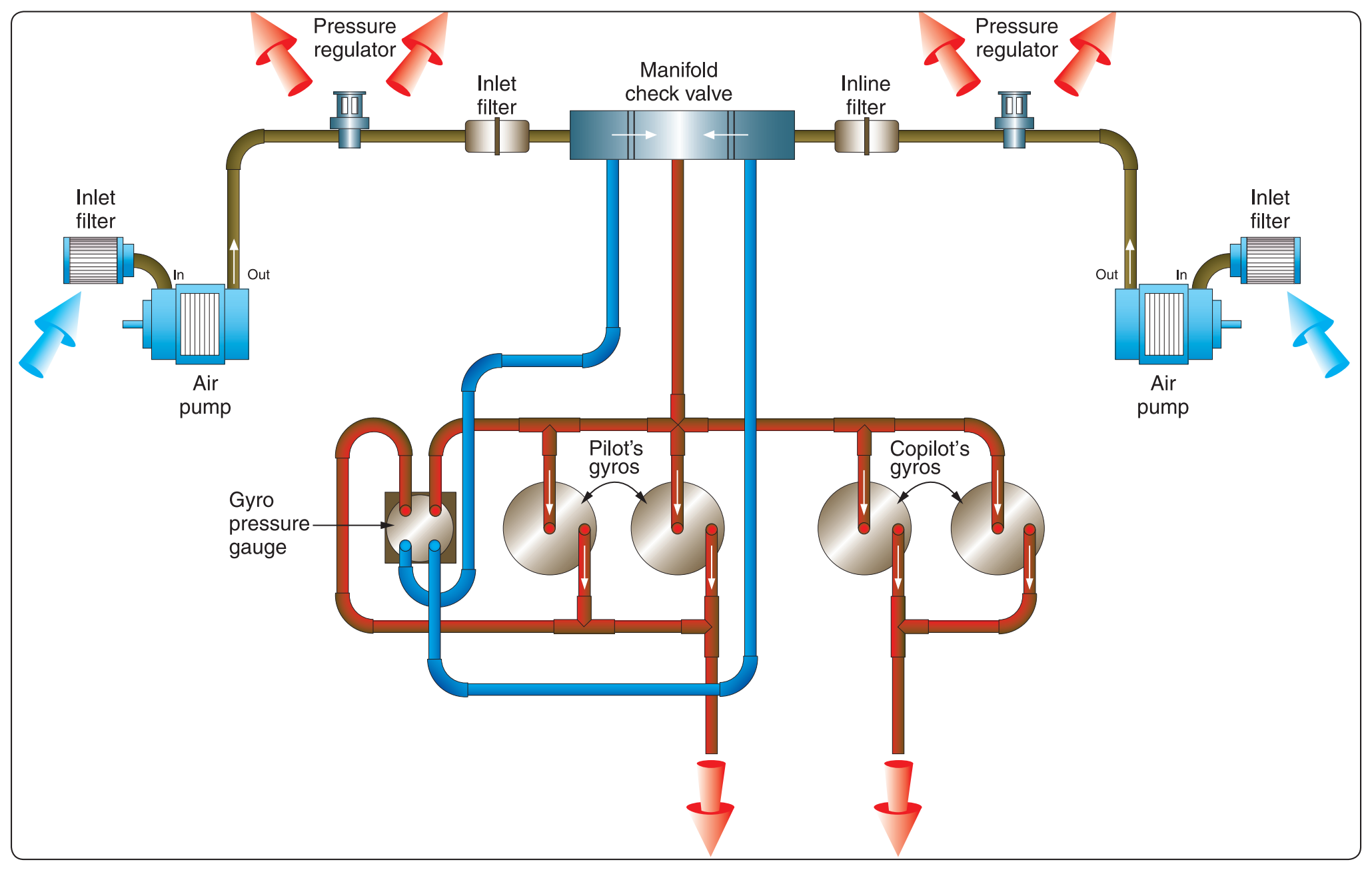
Figure 5-29 is a diagram of the instrument pneumatic system of a twin-engine general aviation airplane. Two dry air pumps are used with filters in their inlets to filter out any contaminants that could damage the fragile carbon vanes in the pump. The discharge air from the pump flows through a regulator, where excess air is bled off to maintain the pressure in the system at the desired level. The regulated air then flows through inline filters to remove any contamination that could have been picked up from the pump, and from there into a manifold check valve. If either engine should become inoperative or either pump should fail, the check valve isolates the inoperative system and the instruments are driven by air from the operating system. After the air passes through the instruments and drives the gyros, it is exhausted from the case. The gyro pressure gauge measures the pressure drop across the instruments.
Electrical Systems
Many general aviation aircraft that use pneumatic attitude indicators use electric rate indicators and/or the reverse. Some instruments identify their power source on their dial, but it is extremely important that pilots consult the POH/AFM to determine the power source of all instruments to know what action to take in the event of an instrument failure. Direct current (D.C.) electrical instruments are available in 14- or 28-volt models, depending upon the electrical system in the aircraft. A.C. is used to operate some attitude gyros and autopilots. Aircraft with only D.C. electrical systems can use A.C. instruments via installation of a solid-state D.C. to A.C. inverter, which changes 14 or 28 volts D.C. into three-phase 115-volt, 400-Hz A.C.
Gyroscopic Instruments
Attitude Indicators
The first attitude instrument (AI) was originally referred to as an artificial horizon, later as a gyro horizon; now it is more properly called an attitude indicator. Its operating mechanism is a small brass wheel with a vertical spin axis, spun at a high speed by either a stream of air impinging on buckets cut into its periphery, or by an electric motor. The gyro is mounted in a double gimbal, which allows the aircraft to pitch and roll about the gyro as it remains fixed in space.
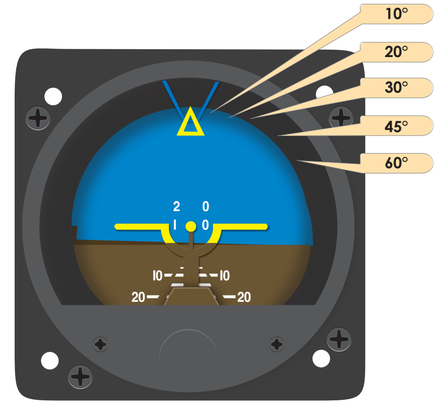
A horizon disk is attached to the gimbals so it remains in the same plane as the gyro, and the aircraft pitches and rolls about it. On early instruments, this was just a bar that represented the horizon, but now it is a disc with a line representing the horizon and both pitch marks and bank-angle lines. The top half of the instrument dial and horizon disc is blue, representing the sky; and the bottom half is brown, representing the ground. A bank index at the top of the instrument shows the angle of bank marked on the banking scale with lines that represent 10°, 20°, 30°, 45°, and 60°. [Figure 5-30] A small symbolic aircraft is mounted in the instrument case so it appears to be flying relative to the horizon. A knob at the bottom center of the instrument case raises or lowers the aircraft to compensate for pitch trim changes as the airspeed changes. The width of the wings of the symbolic aircraft and the dot in the center of the wings represent a pitch change of approximately 2°.