
Chapter 5
Flight Instruments
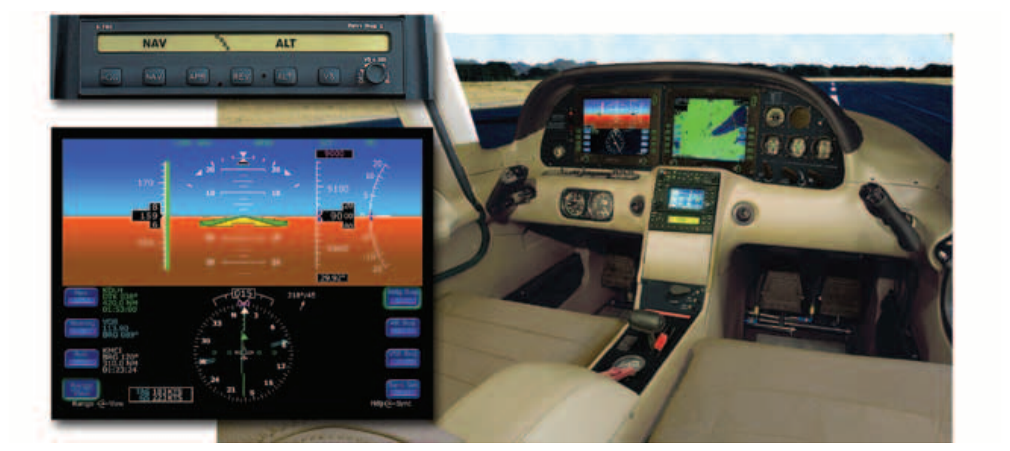
The integrated flight control system integrates and merges various systems into a system operated and controlled by one principal component. Figure 5-41 illustrates key components of the flight control system that was developed from the onset as a fully integrated system comprised of the airframe, autopilot, and FDS. This trend of complete integration, once seen only in large commercial aircraft, is now becoming common in general aviation.
Autopilot Systems
An autopilot is a mechanical means to control an aircraft using electrical, hydraulic, or digital systems. Autopilots can control three axes of the aircraft: roll, pitch, and yaw. Most autopilots in general aviation control roll and pitch.
Autopilots also function using different methods. The first is position based. That is, the attitude gyro senses the degree of difference from a position such as wings level, a change in pitch, or a heading change.
Determining whether a design is position based and/or rate based lies primarily within the type of sensors used. In order for an autopilot to possess the capability of controlling an aircraft’s attitude (i.e., roll and pitch), that system must be provided with constant information on the actual attitude of that aircraft. This is accomplished by the use of several different types of gyroscopic sensors. Some sensors are designed to indicate the aircraft’s attitude in the form of position in relation to the horizon, while others indicate rate (position change over time).
Rate-based systems use the turn-and-bank sensor for the autopilot system. The autopilot uses rate information on two of the aircraft’s three axes: movement about the vertical axis (heading change or yaw) and about the longitudinal axis (roll). This combined information from a single sensor is made possible by the 30° offset in the gyro’s axis to the longitudinal axis.
Other systems use a combination of both position and rate-based information to benefit from the attributes of both systems while newer autopilots are digital. Figure 5-42 illustrates an autopilot by Century.
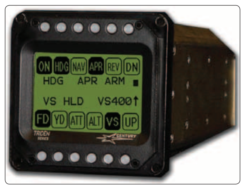
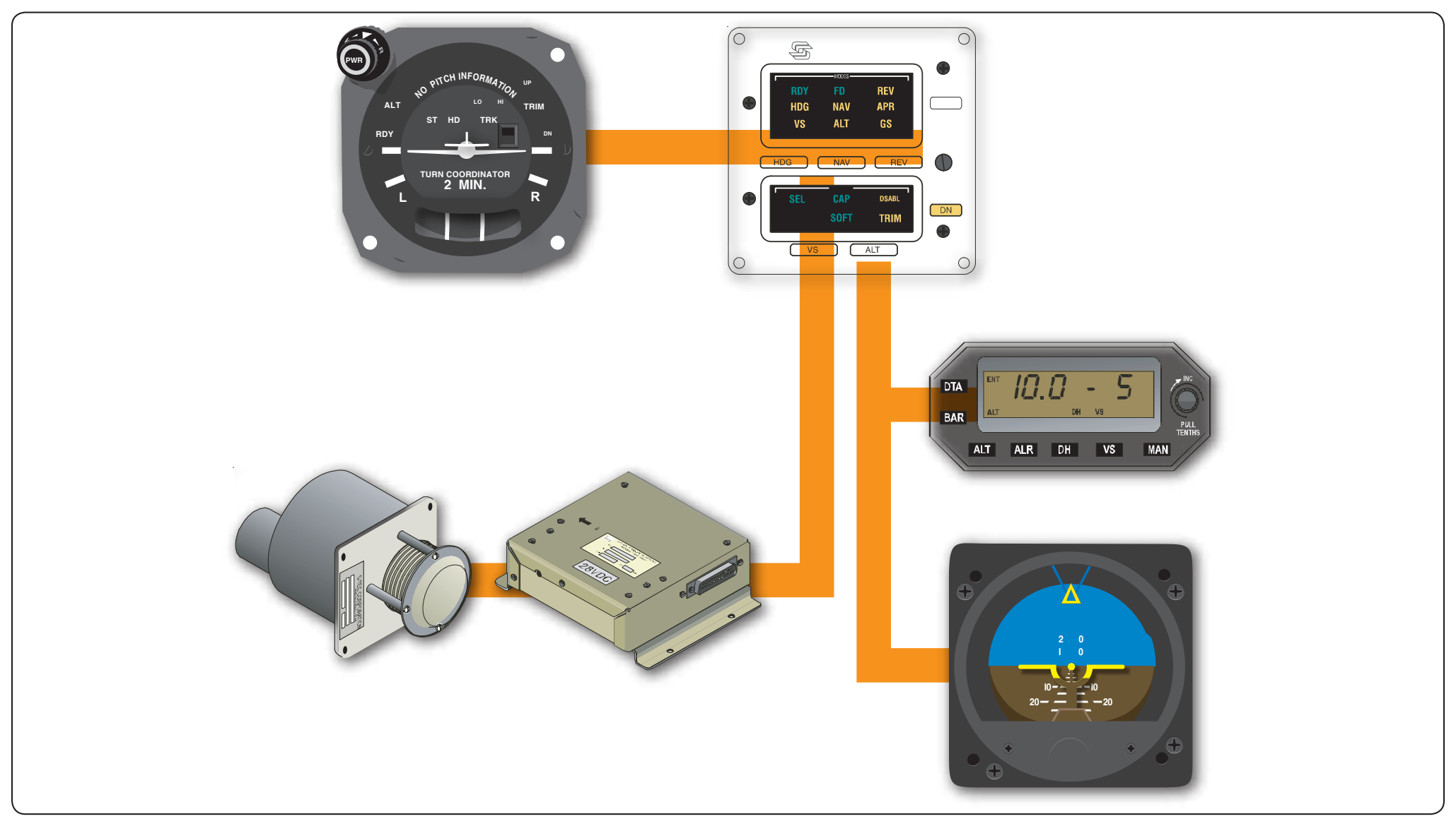
Figure 5-43 is a diagram layout of a rate-based autopilot by S-Tec, which permits the purchaser to add modular capability form basic wing leveling to increased capability.
Flight Management Systems (FMS)
In the mid-1970s, visionaries in the avionics industry such as Hubert Naimer of Universal, and followed by others such as Ed King, Jr., were looking to advance the technology of aircraft navigation. As early as 1976, Naimer had a vision of a “Master Navigation System” that would accept inputs from a variety of different types of sensors on an aircraft and automatically provide guidance throughout all phases of flight.
At that time aircraft navigated over relatively short distances with radio systems, principally VOR or ADF. For long-range flight inertial navigation systems (INS), Omega, Doppler, and Loran were in common use. Short-range radio systems usually did not provide area navigation (RNAV) capability. Long-range systems were only capable of en route point-to-point navigation between manually entered waypoints described as longitude and latitude coordinates, with typical systems containing a limited number of waypoints.
The laborious process of manually entering cryptic latitude and longitude data for each flight waypoint created high crew workloads and frequently resulted in incorrect data entry. The requirement of a separate control panel for each long-range system consumed precious flight deck space and increased the complexity of interfacing the systems with display instruments, flight directors, and autopilots.
The concept employed a master computer interfaced with all of the navigation sensors on the aircraft. A common control display unit (CDU) interfaced with the master computer would provide the pilot with a single control point for all navigation systems, thereby reducing the number of required flight deck panels. Management of the various individual sensors would be transferred from the pilot to the new computer.
Since navigation sensors rarely agree exactly about position, Naimer believed that blending all available sensor position data through a highly sophisticated, mathematical filtering system would produce a more accurate aircraft position. He called the process output the “Best Computed Position.” By using all available sensors to keep track of position, the system could readily provide area navigation capability. The master computer, not the individual sensors, would be integrated into the airplane, greatly reducing wiring complexity.
To solve the problems of manual waypoint entry, a pre-loaded database of global navigation information would be readily accessible by the pilot through the CDU. Using such a system a pilot could quickly and accurately construct a flight plan consisting of dozens of waypoints, avoiding the tedious typing of data and the error potential of latitude/longitude coordinates. Rather than simply navigating point-to-point, the master system would be able to maneuver the aircraft, permitting use of the system for terminal procedures including departures, arrivals, and approaches. The system would be able to automate any aspect of manual pilot navigation of the aircraft. When the first system, called the UNS-1, was released by Universal in 1982, it was called a flight management system (FMS). [Figure 5-44]
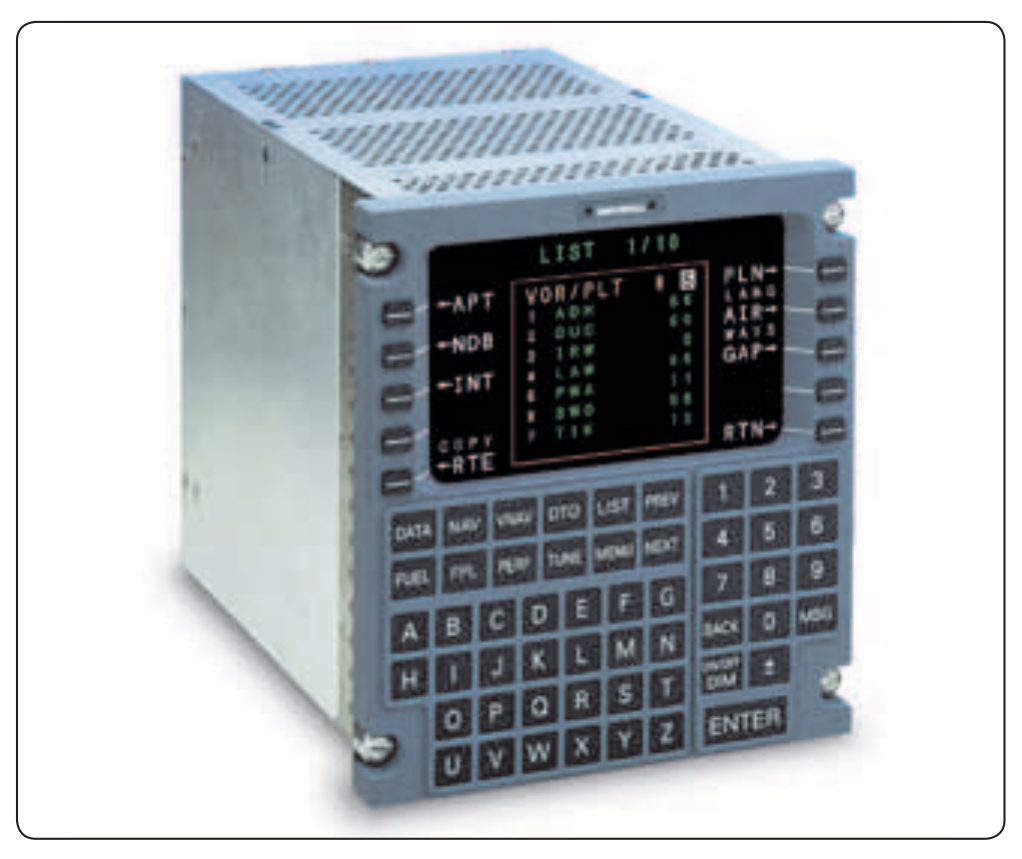
An FMS uses an electronic database of worldwide navigational data including navigation aids, airways and intersections, Standard Instrument Departures (SIDs), STARs, and Instrument Approach Procedures (IAPs) together with pilot input through a CDU to create a flight plan. The FMS provides outputs to several aircraft systems including desired track, bearing and distance to the active waypoint, lateral course deviation and related data to the flight guidance system for the HSI displays, and roll steering command for the autopilot/flight director system. This allows outputs from the FMS to command the airplane where to go and when and how to turn. To support adaptation to numerous aircraft types, an FMS is usually capable of receiving and outputting both analog and digital data and discrete information. Currently, electronic navigation databases are updated every 28 days.