
Chapter 5
Flight Instruments
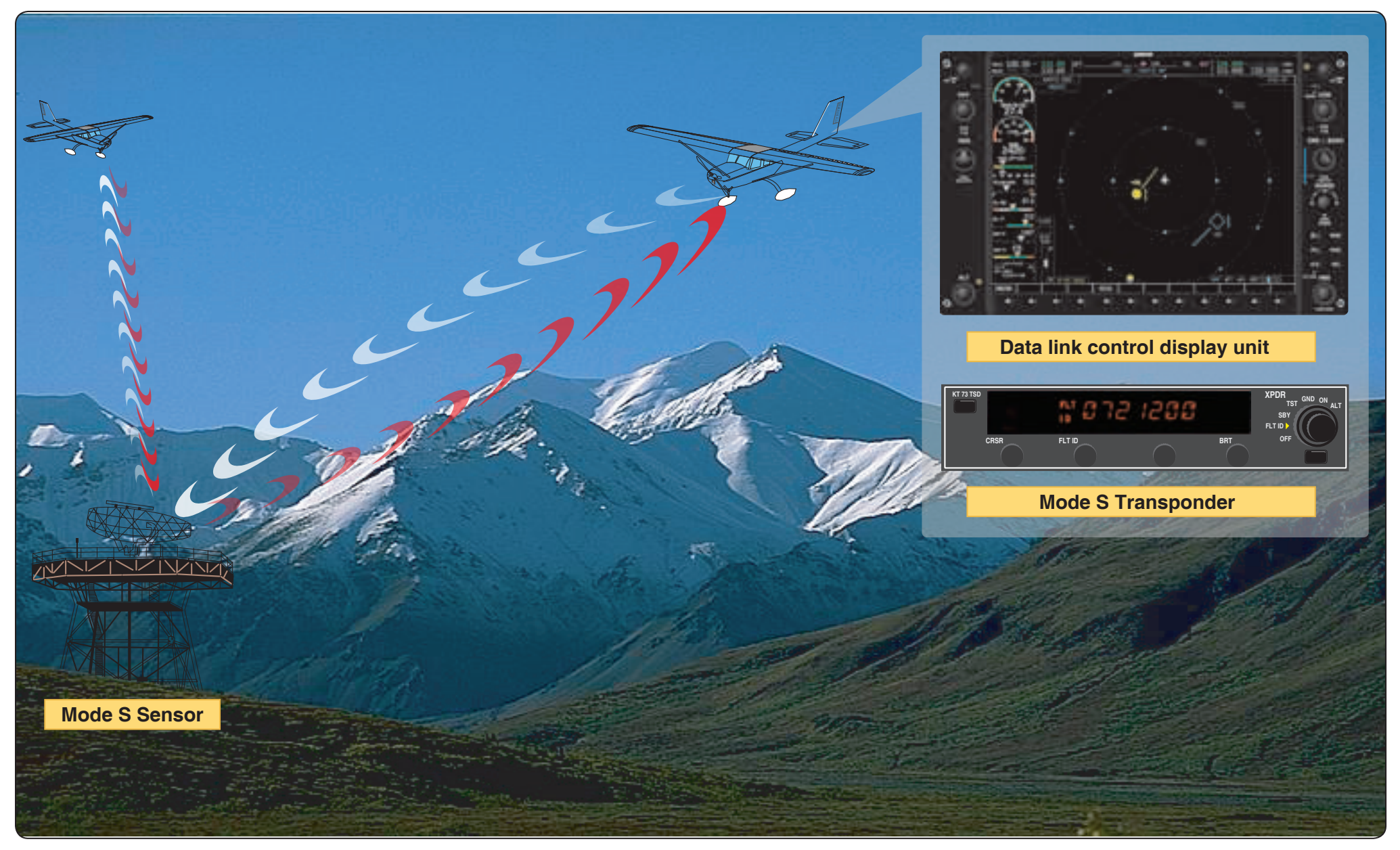
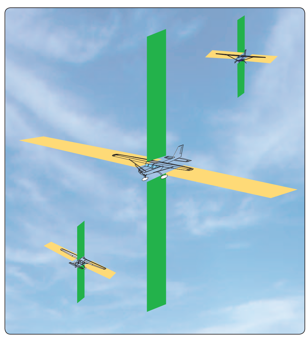
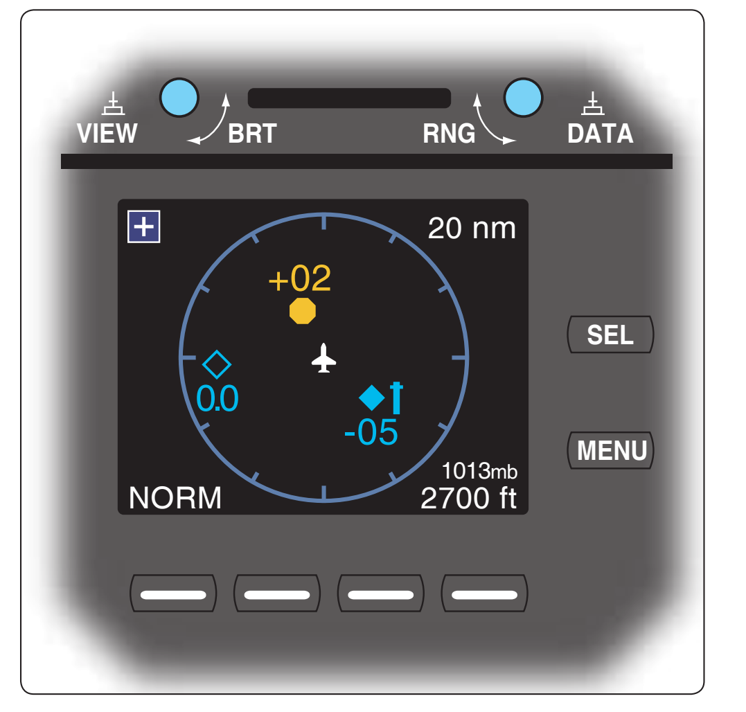
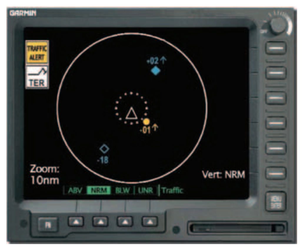
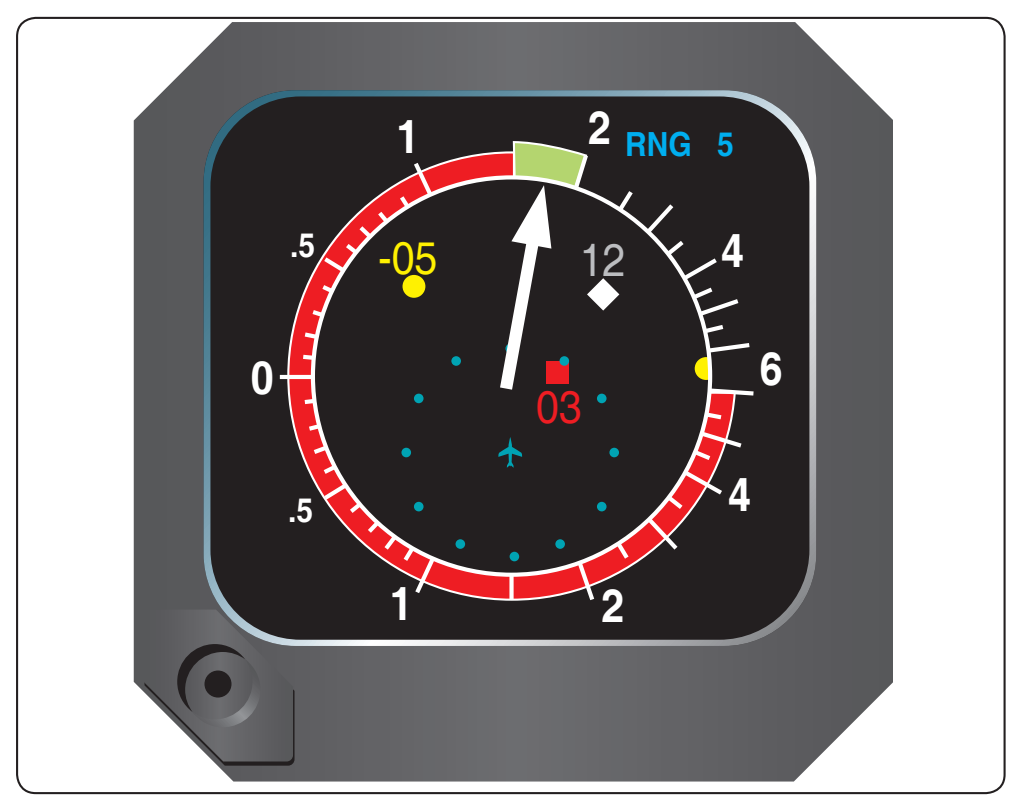
TCAS II is a more sophisticated system which provides the same information of TCAS I. It also analyzes the projected flightpath of approaching aircraft and issues resolution advisories to the pilot to resolve potential mid-air collisions. Additionally, if communicating with another TCAS II equipped aircraft, the two systems coordinate the resolution alerts provided to their respective flight crews. [Figure 5-58]
Terrain Alerting Systems
Ground Proximity Warning System (GPWS)
An early application of technology to reduce controlled flight into terrain (CFIT) was the GPWS. In airline use since the early 1970s, GPWS uses the radio altimeter, speed, and barometric altitude to determine the aircraft’s position relative to the ground. The system uses this information in determining aircraft clearance above the Earth and provides limited predictability about aircraft position relative to rising terrain. It does this based upon algorithms within the system and developed by the manufacturer for different airplanes or helicopters. However, in mountainous areas the system is unable to provide predictive information due to the unusual slope encountered.
This inability to provide predictive information was evidenced in 1999 when a DH-7 crashed in South America. The crew had a GPWS onboard, but the sudden rise of the terrain rendered it ineffective; the crew continued unintentionally into a mountain with steep terrain. Another incident involved Secretary of Commerce Brown who, along with all on board, was lost when the crew flew over rapidly rising terrain where the GPWS capability is offset by terrain gradient. However, the GPWS is tied into and considers landing gear status, flap position, and ILS glideslope deviation to detect unsafe aircraft operation with respect to terrain, excessive descent rate, excessive closure rate to terrain, unsafe terrain clearance while not in a landing configuration, excessive deviation below an ILS glideslope. It also provides advisory callouts.
Generally, the GPWS is tied into the hot bus bar of the electrical system to prevent inadvertent switch off. This was demonstrated in an accident involving a large four-engine turboprop airplane. While on final for landing with the landing gear inadvertently up, the crew failed to heed the GPWS warning as the aircraft crossed a large berm close to the threshold. In fact, the crew attempted without success to shut the system down and attributed the signal to a malfunction. Only after the mishap did the crew realize the importance of the GPWS warning.
Terrain Awareness and Warning System (TAWS)
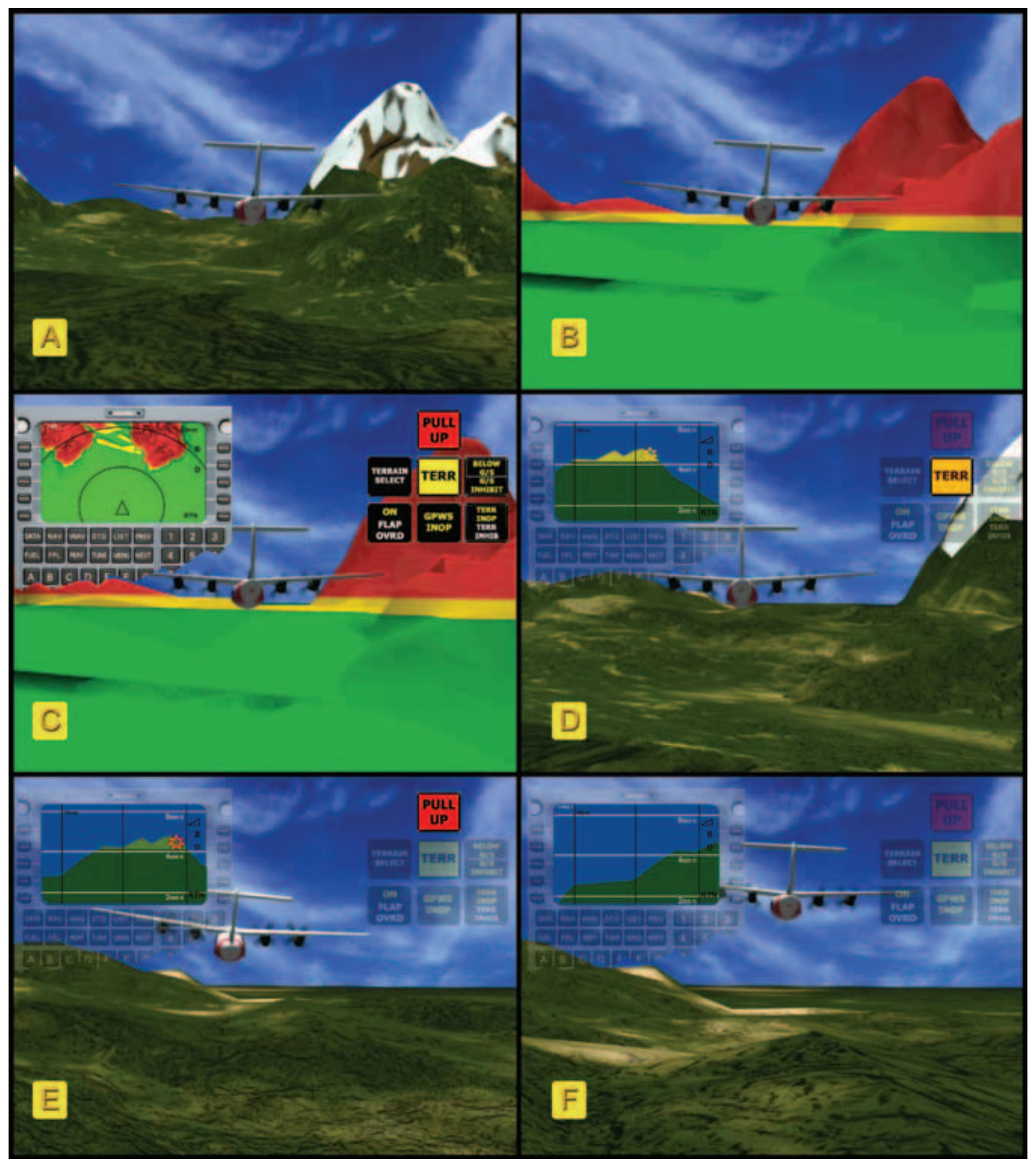
A TAWS uses GPS positioning and a database of terrain and obstructions to provide true predictability of the upcoming terrain and obstacles. The warnings it provides pilots are both aural and visual, instructing the pilot to take specific action. Because TAWS relies on GPS and a database of terrain/obstacle information, predictability is based upon aircraft location and projected location. The system is time based and therefore compensates for the performance of the aircraft and its speed. [Figure 5-59]
Head-Up Display (HUD)
The HUD is a display system that provides a projection of navigation and air data (airspeed in relation to approach reference speed, altitude, left/right and up/down glideslope) on a transparent screen between the pilot and the windshield. The concept of a HUD is to diminish the shift between looking at the instrument panel and outside. Virtually any information desired can be displayed on the HUD if it is available in the aircraft’s flight computer. The display for the HUD can be projected on a separate panel near the windscreen or as shown in Figure 5-60 on an eye piece. Other information may be displayed, including a runway target in relation to the nose of the aircraft, which allows the pilot to see the information necessary to make the approach while also being able to see out the windshield.
Required Navigation Instrument System Inspection
Systems Preflight Procedures
Inspecting the instrument system requires a relatively small part of the total time required for preflight activities, but its importance cannot be overemphasized. Before any flight involving aircraft control by instrument reference, the pilot should check all instruments and their sources of power for proper operation.