Chapter 5
Flight Instruments
Safety Systems
Radio Altimeters
A radio altimeter, commonly referred to as a radar altimeter, is a system used for accurately measuring and displaying the height above the terrain directly beneath the aircraft. It sends a signal to the ground and processes the timed information. Its primary application is to provide accurate absolute altitude information to the pilot during approach and landing. In advanced aircraft today, the radar altimeter also provides its information to other onboard systems such as the autopilot and flight directors while they are in the glideslope capture mode below 200-300 feet above ground level (AGL).
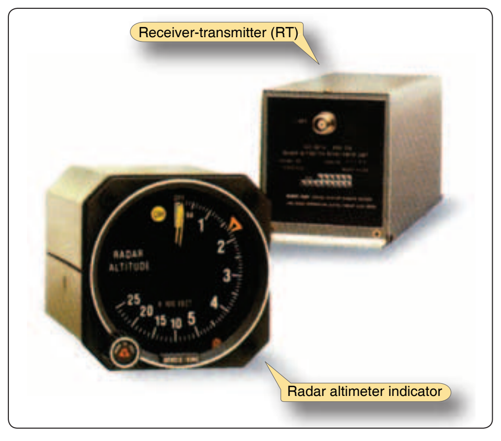
A typical system consists of a receiver-transmitter (RT) unit, antenna(s) for receiving and transmitting the signal, and an indicator. [Figure 5-51] Category II and III precision approach procedures require the use of a radar altimeter and specify the exact minimum height above the terrain as a decision height (DH) or radio altitude (RA).
Traffic Advisory Systems
Traffic Information System
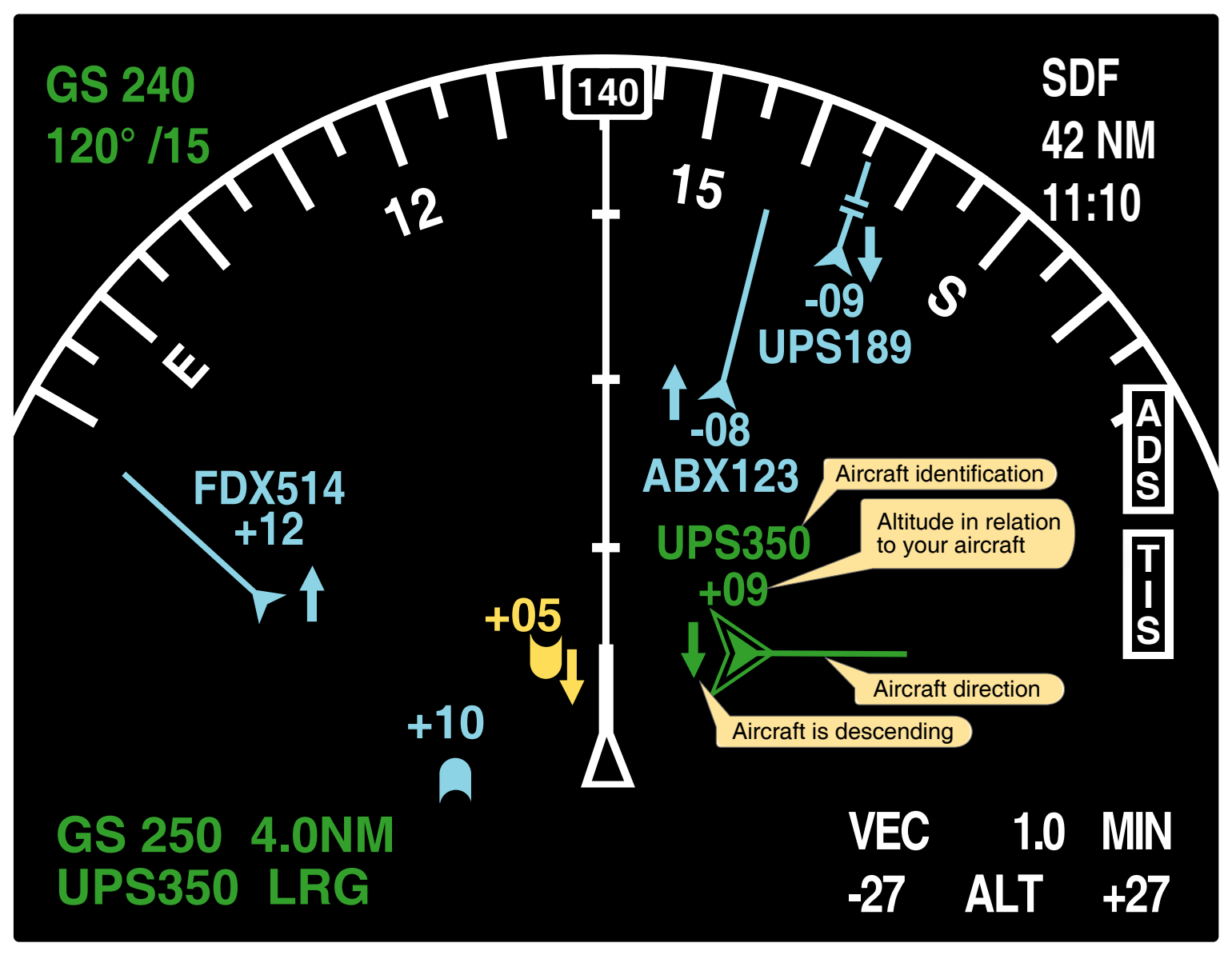
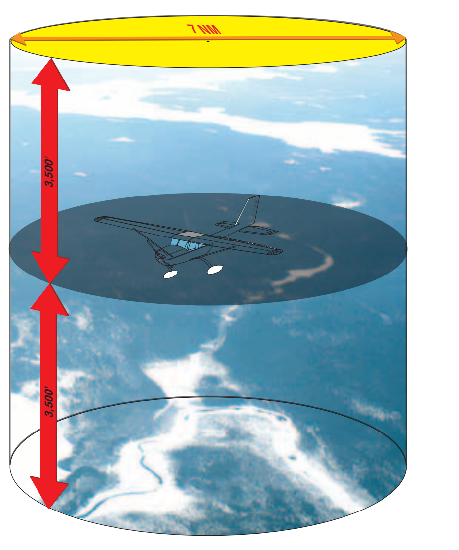
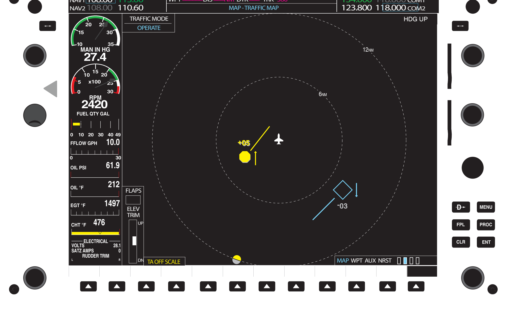
The Traffic Information Service (TIS) is a ground-based service providing information to the flight deck via data link using the S-mode transponder and altitude encoder. TIS improves the safety and efficiency of “see and avoid” flight through an automatic display that informs the pilot of nearby traffic. The display can show location, direction, altitude and the climb/descent trend of other transponder-equipped aircraft. TIS provides estimated position, altitude, altitude trend, and ground track information for up to several aircraft simultaneously within about 7 NM horizontally, 3,500 feet above and 3,500 feet below the aircraft. [Figure 5-52] This data can be displayed on a variety of MFDs. [Figure 5-53]
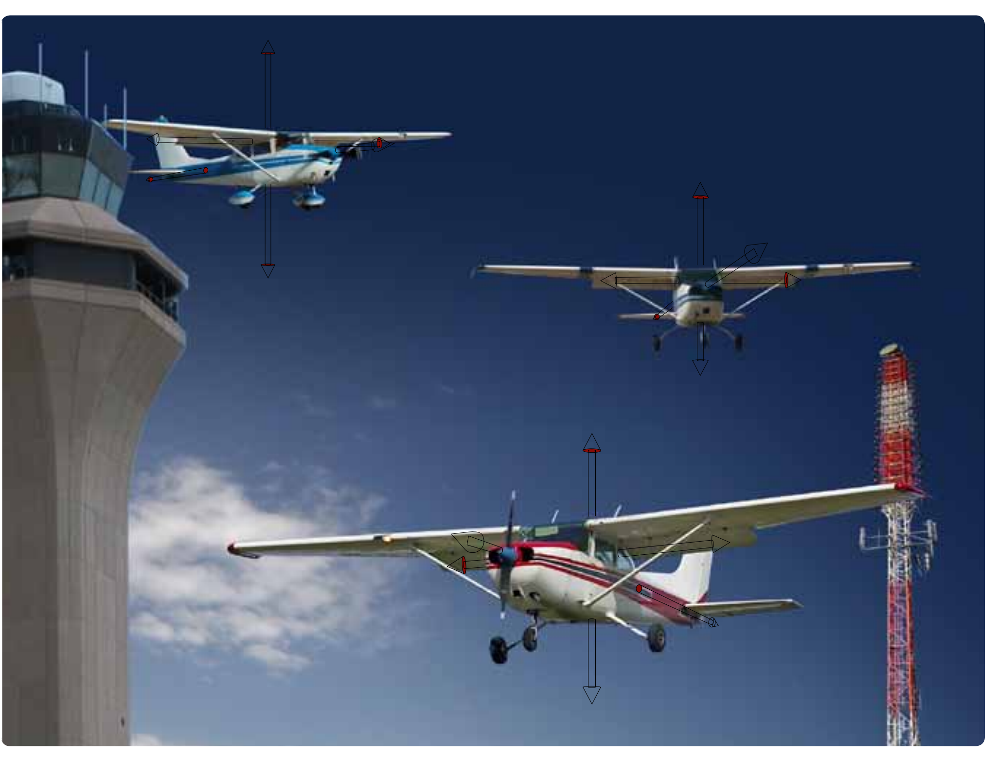
Figure 5-54 displays the pictorial concept of the traffic information system. Noteworthy is the requirement to have Mode S and that the ground air traffic station processes the Mode S signal.
Traffic Alert Systems
Traffic alert systems receive transponder information from nearby aircraft to help determine their relative position to the equipped aircraft. They provide three-dimensional location of other aircraft [Figures 5-55, 5-56, and 5-57] and are cost effective alternatives to TCAS equipage for smaller aircraft.
Traffic Avoidance Systems
Traffic Alert and Collision Avoidance System (TCAS)
The TCAS is an airborne system developed by the FAA that operates independently from the ground-based ATC system. TCAS was designed to increase flight deck awareness of proximate aircraft and to serve as a “last line of defense” for the prevention of mid-air collisions.
There are two levels of TCAS systems. TCAS I was developed to accommodate the general aviation (GA) community and the regional airlines. This system issues traffic advisories (TAs) to assist pilots in visual acquisition of intruder aircraft. TCAS I provides approximate bearing and relative altitude of aircraft with a selectable range. It provides the pilot with TA alerting him or her to potentially conflicting traffic. The pilot then visually acquires the traffic and takes appropriate action for collision avoidance.