
Chapter 6
Airplane Attitude Instrument Flying
Scan left to the airspeed tape and verify that the airspeed is as desired, then return back to the center of the display. Scan right to the altimeter tape. Verify that the desired altitude is being maintained. If it is not, make the appropriate pitch change and verify the result. Once the desired altitude has been verified, return to the center of the display. Transition down to the heading indicator to verify the desired heading. When the heading has been confirmed, scan to the center of the display.
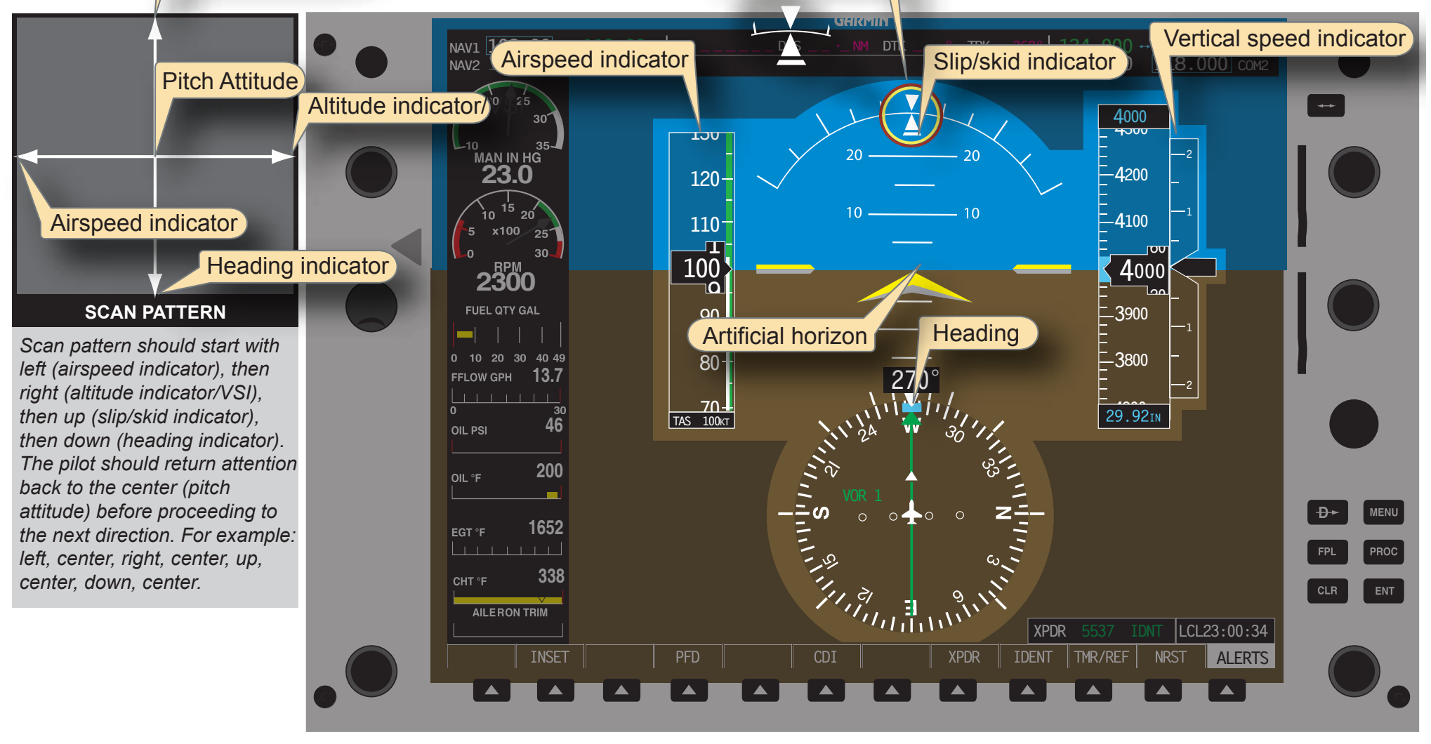
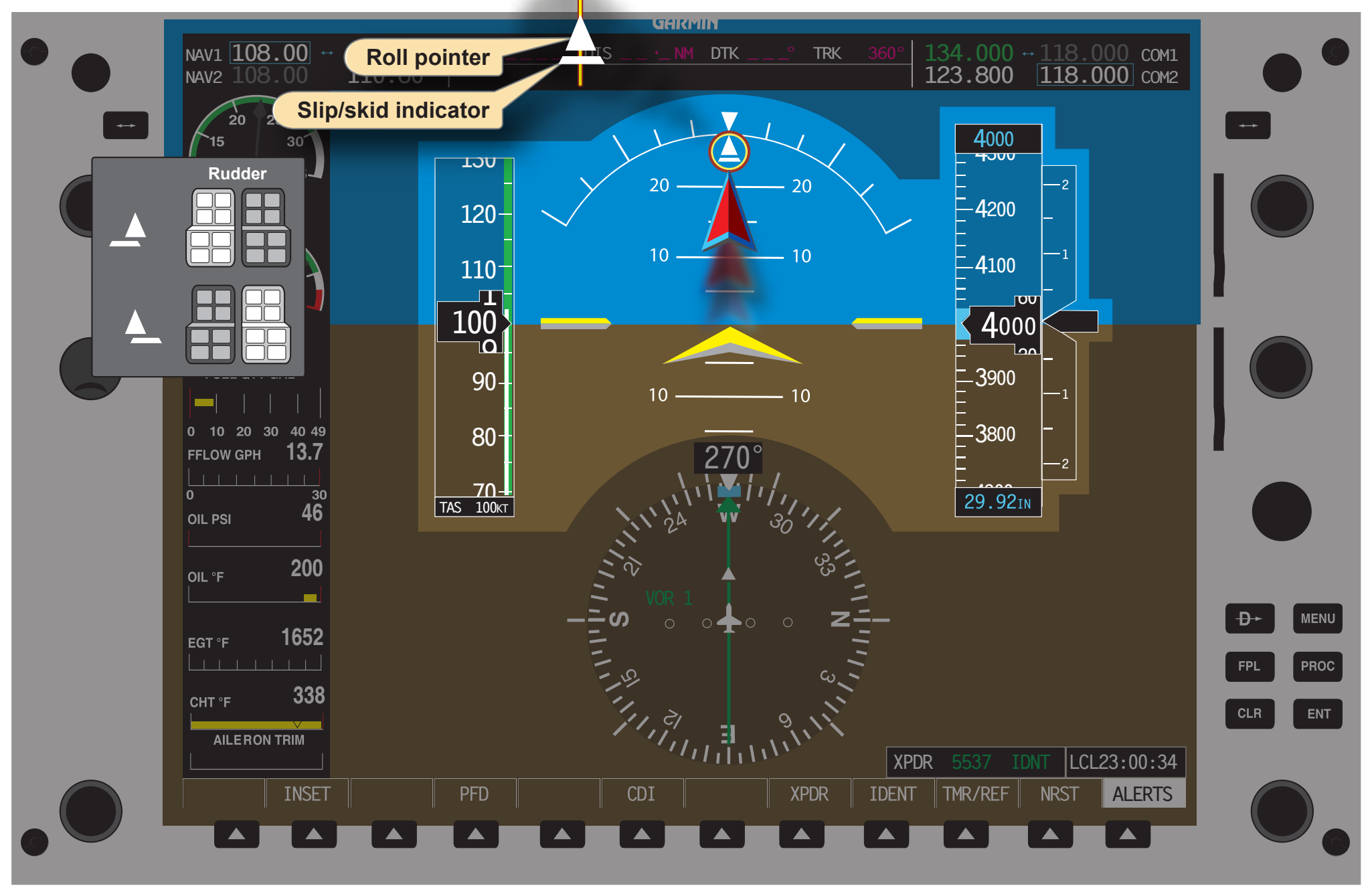
It is also important to include the engine indications in the scan. Individualized scan methods may require adjustment if engine indications are presented on a separate MFD. A modified radial scan can be performed to incorporate these instruments into the scan pattern. Another critical component to include in the scan is the moving map display located on the MFD. To aid in situational awareness and facilitate a more centralized scan, a smaller inset map can be displayed in the lower left corner of the PFD screen.
Trend Indicators
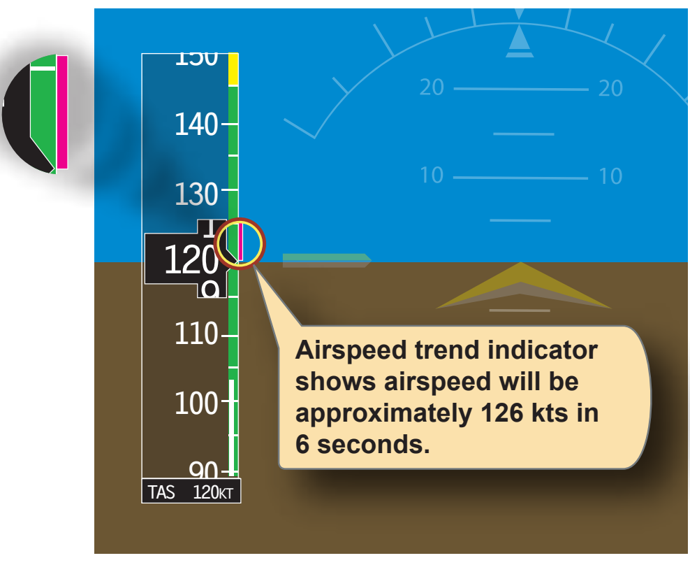
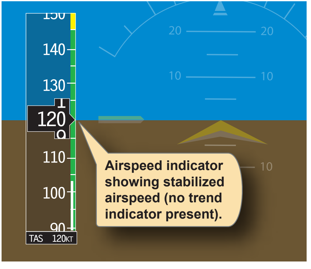
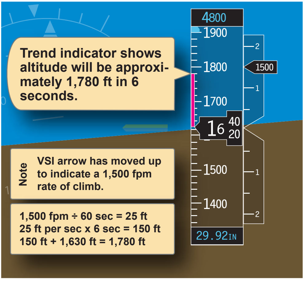
One improvement the glass panel displays brought to the general aviation industry is the trend vector. Trend vectors are colored lines that appear on the airspeed and altitude tapes, as well as on the turn rate indicator. The color of the line may vary depending on the airplane manufacturer. For example, on a Cirrus SR-20, the trend vector lines are magenta and on the B-737 they are green. These colored lines indicate what the associated airspeed, altitude, or heading will be in 6 seconds for the Cirrus SR-20 and 10 seconds for the B-737 if the current rate is maintained. The example shown in Figure 6-35 uses the color and data that represents the trend vector for a Cirrus SR-20. The trend vector is not displayed if there is no change to the associated tape and the value remains constant [Figure 6-36] or if there is a failure in some portion of the system that would preclude the vector from being determined.
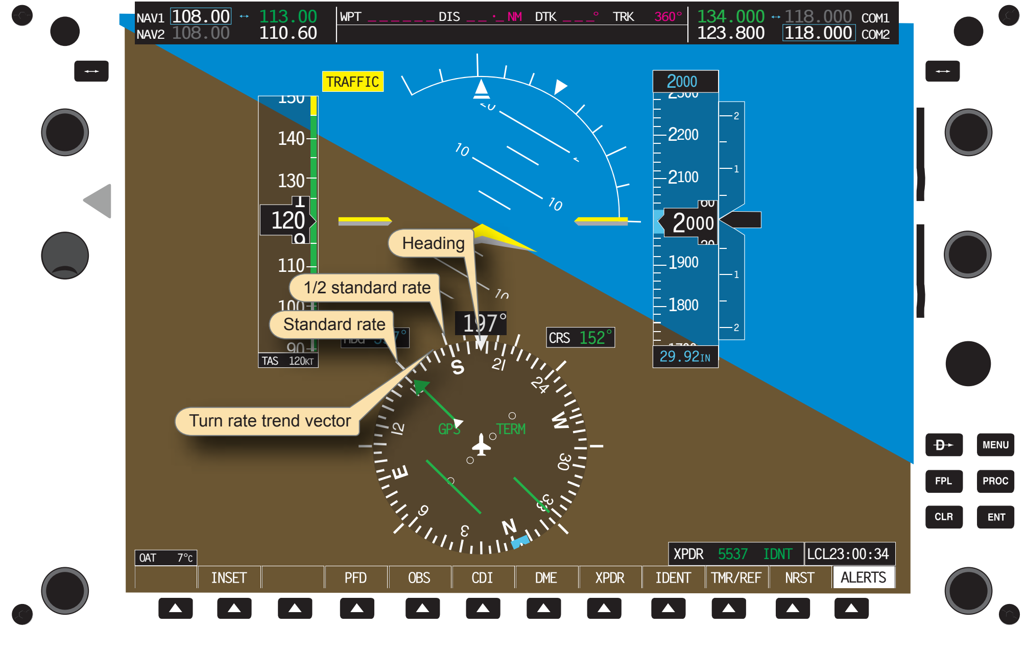
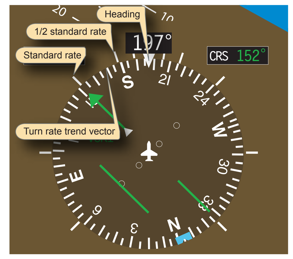
Trend vectors are a very good source of information for the new instrument rated pilot(s). Pilots who utilize good scanning techniques can pick up subtle deviations from desired parameters and make small correction to the desired attitude. As soon as a trend is indicated on the PFD, a conscientious pilot can adjust to regain the desired attitude. [Figure 6-37] Another advancement in attitude instrument flying is the turn rate trend indicator. As in the cases of airspeed, altitude, and vertical speed trend indicators, the turn rate trend indicator depicts what the aircraft’s heading will be in 6 seconds. While examining the top of the heading indicator, notice two white lines on the exterior of the compass rose. [Figure 6-38] These two tick marks located on both sides of the top of the heading indicator show half-standard rate turns as well as standard rate turns.
In Figure 6-39, when the aircraft begins its turn to the left, the magenta trend indicator elongates proportionally with the rate of turn. To initiate a half-standard rate turn, position the indicator on the first tick mark. A standard rate turn would be indicated by the trend indicator extending to the second tick mark. A turn rate in excess of standard rate would be indicated by the trend indicator extending past the second tick mark. This trend indicator shows what the aircraft’s heading will be in 6 seconds, but is limited to indicate no more than 24° in front of the aircraft or 4° per second. When the aircraft exceeds a turning rate of 25° in 6 seconds, the trend indicator has an arrowhead attached to it.
Trend indicators are very useful when leveling off at a specific altitude, when rolling out on a heading, or when stabilizing airspeed. One method of determining when to start to level off from a climb or descent is to start leveling at 10 percent of the vertical speed rate prior to the desired altitude.
As the aircraft approaches the desired altitude, adjust the pitch attitude to keep the trend indicator aligned with the target altitude. As the target approaches, the trend indicator gradually shrinks until altitude stabilizes. Trend indicators should be used as a supplement, not as a primary means of determining pitch change.
Common Errors
Fixation
Fixation, or staring at one instrument, is a common error observed in pilots first learning to utilize trend indicators. The pilot may initially fixate on the trend indicator and make adjustments with reference to that alone. Trend indicators are not the only tools to aid the pilot in maintaining the desired power or attitude; they should be used in conjunction with the primary and supporting instruments in order to better manage the flight. With the introduction of airspeed tapes, the pilot can monitor airspeed to within one knot. Fixation can lead to attempting to keep the airspeed to an unnecessarily tight tolerance. There is no need to hold airspeed to within one knot; the Instrument Rating Practical Test Standards (PTS) allows greater latitude.
Omission
Another common error associated with attitude instrument flying is omission of an instrument from the cross-check. Due to the high reliability of the PFD and associated components, pilots tend to omit the stand-by instruments as well as the magnetic compass from their scans. An additional reason for the omission is the position of the stand-by instruments. Pilots should continue to monitor the stand-by instruments in order to detect failures within those systems. One of the most commonly omitted instruments from the scan is the slip/skid indicator.