
Chapter 6
Airplane Attitude Instrument Flying
There are supporting instruments associated with bank as well. The turn rate trend indicator shows the pilot when the aircraft is changing heading. The magnetic compass is also useful for maintaining a heading; however, it is influenced by several errors in various phases of flight.
Primary Yaw
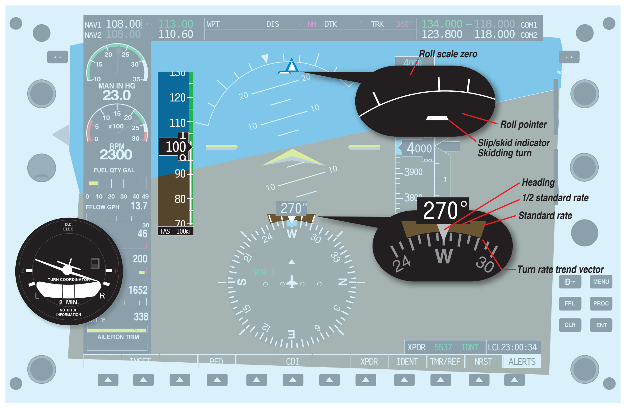
The slip/skid indicator is the primary instrument for yaw. It is the only instrument that can indicate if the aircraft is moving through the air with the longitudinal axis of the aircraft aligned with the relative wind.
Primary Power
The primary power instrument for straight-and-level flight is the airspeed indicator. The main focus of power is to maintain a desired airspeed during level flight. No other instrument delivers instantaneous indication.
Learning the primary and supporting instruments for each variable is the key to successfully mastering attitude instrument flying. At no point does the primary and supporting method devalue the importance of the attitude indicator or the power instruments. All instruments (control, performance, primary, and supporting) must be utilized collectively.
Fundamental Skills of Attitude Instrument Flying
When first learning attitude instrument flying, it is very important that two major skills be mastered. Instrument cross-check and instrument interpretation comprise the foundation for safely maneuvering the aircraft by reference to instruments alone. Without mastering both skills, the pilot is not able to maintain precise control of aircraft attitude.
Instrument Cross-Check
The first fundamental skill is cross-checking (also call “scanning”). Cross-checking is the continuous observation of the indications on the control and performance instruments. It is imperative that the new instrument pilot learn to observe and interpret the various indications in order to control the attitude and performance of the aircraft. Due to the configuration of some glass panel displays, such as the Garmin G1000, one or more of the performance instruments may be located on an MFD installed to the right of the pilot’s direct forward line of sight.
How a pilot gathers the necessary information to control the aircraft varies by individual pilot. No specific method of cross-checking (scanning) is recommended; the pilot must learn to determine which instruments give the most pertinent information for any particular phase of a maneuver. With practice, the pilot is able to observe the primary instruments quickly and cross-check with the supporting instruments in order to maintain the desired attitude. At no time during instrument flying should the pilot stop cross-checking the instrumentation.
Scanning Techniques
Since most of the primary and supporting aircraft attitude information is displayed on the PFD, standard scanning techniques can be utilized. It is important to remember to include the stand-by flight instruments as well as the engine indications in the scan. Due to the size of the attitude instrument display, scanning techniques have been simplified because the attitude indicator is never out of peripheral view.
Selected Radial Cross-Check
The radial scan is designed so that your eyes remain on the attitude indicator 80–90 percent of the time. The remainder of the time is spent transitioning from the attitude indicator to the various other flight instruments. [Figure 6-33]
The radial scan pattern works well for scanning the PFD. The close proximity of the instrument tape displays necessitates very little eye movement in order to focus in on the desired instrument. While the eyes move in any direction, the extended artificial horizon line allows the pilot to keep the pitch attitude in his or her peripheral vision. This extended horizon line greatly reduces the tendency to fixate on one instrument and completely ignore all others. Because of the size of the attitude display, some portion of the attitude indicator is always visible while viewing another instrument display on the PFD.
Starting the Scan
Start the scan in the center of the PFD on the yellow chevron. Note the pitch attitude and then transition the eyes upward to the slip/skid indicator. Ensure that the aircraft is coordinated by aligning the split triangle symbol. The top of the split triangle is referred to as the roll pointer. The lower portion of the split triangle is the slip/skid indicator. If the lower portion of the triangle is off to one side, step on the rudder pedal on the same side to offset it. [Figure 6-34 NOTE: The aircraft is not changing heading. There is no trend vector on the turn rate indicator.]
While scanning that region, check the roll pointer and assure that the desired degree of roll is being indicated on the bank scale. The roll index and the bank scale remain stationary at the top of the attitude indicator. The index is marked with angles of 10°, 20°, 30°, 45°, and 60° in both directions. If the desired bank angle is not indicated, make the appropriate aileron corrections. Verify the bank angle is correct and continue scanning back to the yellow chevron.