
Chapter 6
Airplane Attitude Instrument Flying
Power control needs to be learned from the beginning of flight training. Attitude instrument flying demands increased precision when it comes to power control. As experience increases, pilots begin to know approximately how much change in throttle position is required to produce the desired change in airspeed. Different aircraft demand differing amounts of throttle change to produce specific performance. It is imperative that the pilot make the specific changes on the power instruments and allow the performance to stabilize. Avoid the tendency to overcontrol.
One common error encountered with glass panel displays is associated with the precision of the digital readouts. This precision causes pilots to focus too much attention on establishing the exact power setting.
Control and power instruments are the foundation for precise attitude instrument flying. The keys to attitude instrument flying are establishing the desired aircraft attitude on the attitude indicator and selecting the desired engine output on the power instruments. Cross-checking is the vital ingredient in maintaining precise attitude instrument flight.
Attitude Instrument Flying—Primary and Supporting Method
The second method for performing attitude instrument flight is a direct extension of the control/power method. By utilizing the primary and supporting flight instruments in conjunction with the control and power instruments, the pilot can precisely maintain aircraft attitude. This method utilizes the same instruments as the control/power method; however, it focuses more on the instruments that depict the most accurate indication for the aspect of the aircraft attitude being controlled. The four key elements (pitch, bank, roll, and trim) are discussed in detail.
Similar to the control/power method, all changes to aircraft attitude need to be made using the attitude indicator and the power instruments (tachometer, manifold pressure gauge, etc.). The following explains how each component of the aircraft attitude is monitored for performance.
Pitch Control
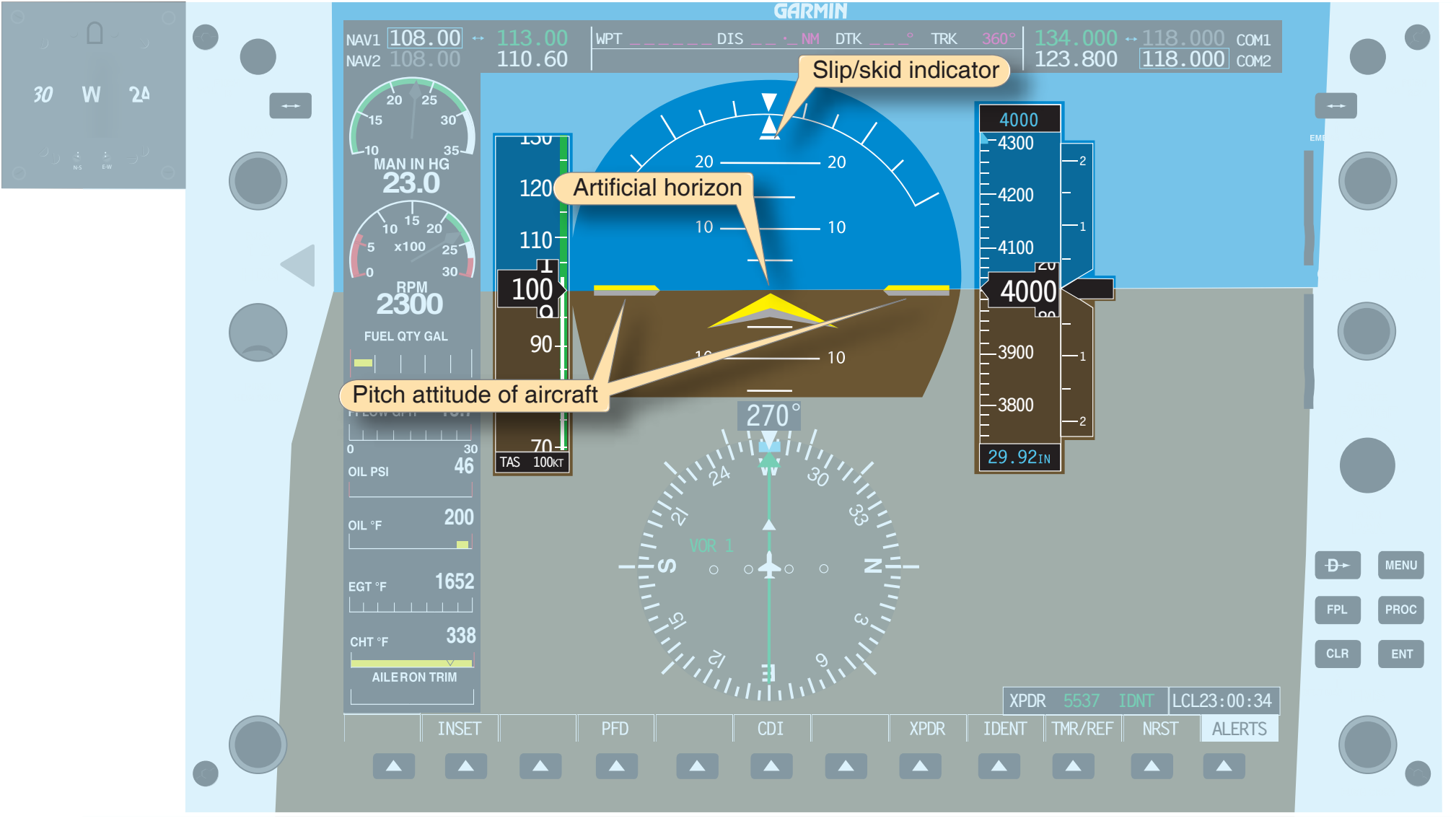
The pitch of the aircraft refers to the angle between the longitudinal axis of the aircraft and the natural horizon. When flying in instrument meteorological conditions (IMC), the natural horizon is unavailable for reference and an artificial horizon is utilized in its place. [Figure 6-30] The only instrument capable of depicting the aircraft attitude is the attitude indicator displayed on the PFD. The attitude and heading reference system (AHRS) is the engine that drives the attitude display. The AHRS unit is capable of precisely tracking minute changes in the pitch, bank, and yaw axes, thereby making the PFD very accurate and reliable. The AHRS unit determines the angle between the aircraft’s longitudinal axis and the horizon line on initialization. There is no need or means for the pilot to adjust the position of the yellow chevron, which represents the nose of the aircraft.
Straight-and-Level Flight
In straight-and-level flight, the pilot maintains a constant altitude, airspeed and, for the most part, heading for extended periods of time. To achieve this, the three primary instruments that need to be referenced in order to maintain these three variables are the altitude, airspeed, and heading indicators.
Primary Pitch
When the pilot is maintaining a constant altitude, the primary instrument for pitch is the altimeter. As long as the aircraft maintains a constant airspeed and pitch attitude, the altitude should remain constant.
Two factors that cause the altitude to deviate are turbulence and momentary distractions. When a deviation occurs, a change in the pitch needs to be made on the attitude indicator. Small deviations require small corrections, while large deviations require larger corrections. Pilots should avoid making large corrections that result in rapid attitude changes, for this may lead to spatial disorientation. Smooth, timely corrections should be made to bring the aircraft back to the desired attitude.
Pay close attention to indications on the PFD. An increase in pitch of 2.5° produces a climb rate of 450 feet per minute (fpm). Small deviations do not require large attitude changes. A rule of thumb for correcting altitude deviations is to establish a change rate of twice the altitude deviation, not to exceed 500 fpm. For example, if the aircraft is off altitude by 40 feet, 2 40 = 80 feet, so a descent of approximately 100 fpm allows the aircraft to return to the desired altitude in a controlled, timely fashion.
In addition to the primary instrument, there are also supporting instruments that assist the pilot in cross-checking the pitch attitude. The supporting instruments indicate trend, but they do not indicate precise attitude indications. Three instruments (vertical speed, airspeed, and altitude trend tape) indicate when the pitch attitude has changed and that the altitude is changing. [Figure 6-31] When the altitude is constant, the VSI and altitude trend tape are not shown on the PFD. When these two trend indicators are displayed, the pilot is made aware that the pitch attitude of the aircraft has changed and may need adjustment. Notice in Figure 6-31 that the aircraft is descending at a rate of 500 fpm.
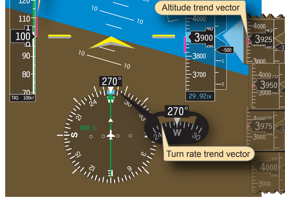
The instrument cross-check necessitates utilizing these supporting instruments to better manage altitude control. The VSI and trend tape provide the pilot with information regarding the direction and rate of altitude deviations. The pilot is thus able to make corrections to the pitch attitude before a large deviation in altitude occurs. The airspeed indicator depicts an increase if the pitch attitude is lowered. Conversely, when the pitch attitude increases, the pilot should note a decrease in the airspeed.
Primary Bank
When flying in IMC, pilots maintain preplanned or assigned headings. With this in mind, the primary instrument for bank angle is the heading indicator. Heading changes are displayed instantaneously. The heading indicator is the only instrument that displays the current magnetic heading, provided that it is matched to the magnetic compass with all deviation adjustments accounted for. [Figure 6-32]