
Chapter 7
Airplane Basic Flight Maneuvers
Timed turns become essential when controlling the aircraft with a loss of the heading indicator. This may become necessary due to a loss of the AHRS unit or the magnetometer. In any case, the magnetic compass is still available for navigation. The reason for timed turns instead of magnetic compass turns is the simplicity of the maneuver. Magnetic compass turns require the pilot to take into account various errors associated with the compass; timed turns do not.
Prior to initiating a turn, determine if the standard rate indication on the turn rate indicator actually delivers a 3 degrees per second turn. To accomplish this, a calibration must be made. Establish a turn in either direction at the indicated standard rate. Start the digital timer as the compass rolls past a cardinal heading. Stop the timer once the compass card rolls through another cardinal heading. Roll wings level and compute the rate of turn. If the turn rate indicator is calibrated and indicating correctly, 90° of heading change should take 30 seconds. If the time taken to change heading by 90° is more or less than 30 seconds, then a deflection above or below the standard rate line needs to be made to compensate for the difference. Once the calibration has been completed in one direction, proceed to the opposite direction. When both directions have been calibrated, apply the calibrated calculations to all timed turns.
In order to accomplish a timed turn, the amount of heading change needs to be established. For a change in heading from 120° to a heading of 360°, the pilot calculates the difference and divides that number by 3. In this case, 120° divided by 3° per second equals 40 seconds. This means that it would take 40 seconds for an aircraft to change heading 120° if that aircraft were held in a perfect standard rate turn. Timing for the maneuver should start as the aircraft begins rolling into the standard rate turn. Monitor all flight instruments during this maneuver. The primary pitch instrument is the altimeter. The primary power instrument is the ASI and the primary bank instrument is the turn rate indicator.
Once the calculated time expires, start a smooth coordinated roll-out. As long as the pilot utilizes the same rate of roll-in as roll-out, the time it takes for both will not need to be included in the calculations. With practice, the pilot should level the wings on the desired heading. If any deviation has occurred, make small corrections to establish the correct heading.
Compass Turns
The magnetic compass is the only instrument that requires no other source of power for operation. In the event of an AHRS or magnetometer failure, the magnetic compass is the instrument the pilot uses to determine aircraft heading. For a more detailed explanation on the use of the magnetic compass, see page 7-21.
Steep Turns
For the purpose of instrument flight training, a steep turn is defined as any turn in excess of standard rate. A standard rate turn is defined as 3 degrees per second. The bank angle that equates to a turn rate of 3 degrees per second varies according to airspeed. As airspeed increases, the bank angle must be increased. The exact bank angle that equates to a standard rate turn is unimportant. Normal standard rate turn bank angles range from 10° to 20°. The goal of training in steep turn maneuvers is pilot proficiency in controlling the aircraft with excessive bank angles.
Training in excessive bank angles challenges the pilot in honing cross-checking skills and improves altitude control throughout a wider range of flight attitudes. Although the current instrument flight check practical test standards (PTS) do not call for a demonstration of steep turns on the certification check flight, this does not eliminate the need for the instrument pilot-in-training to demonstrate proficiency to an instructor.
Training in steep turns teaches the pilot to recognize and to adapt to rapidly changing aerodynamic forces that necessitate an increase in the rate of cross-checking all flight instruments. The procedures for entering, maintaining, and exiting a steep turn are the same as for shallower turns. Proficiency in instrument cross-check and interpretation is increased due to the higher aerodynamic forces and increased speed at which the forces are changing.
Performing the Maneuver
To enter a steep turn to the left, roll into a coordinated 45° bank turn to the left. An advantage that glass panel displays have over analog instrumentation is a 45° bank indication on the roll scale. This additional index on the roll scale allows the pilot to precisely roll into the desired bank angle instead of having to approximate it as is necessary with analog instrumentation. [Figure 7-68]
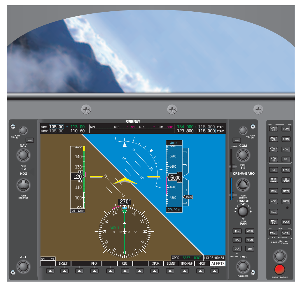
As soon as the bank angle increases from level flight, the vertical component of lift begins to decrease. If the vertical component of lift is allowed to continue to decrease, a pronounced loss of altitude is indicated on the altimeter along with the VSI tape, as well as the altitude trend indicator. Additionally, the airspeed begins to increase due to the lowered pitch attitude. It is very important to have a comprehensive scan developed prior to training in steep turns. Utilization of all of the trend indicators, as well the VSI, altimeter, and ASI, is essential in learning to fly steep turns by reference to instruments alone.
In order to avoid a loss of altitude, the pilot begins to slowly increase back pressure on the control yoke in order to increase the pitch attitude. The pitch change required is usually no more than 3 degrees to 5 degrees, depending on the type of aircraft. As the pilot increases back pressure, the angle of attack increases, thus increasing the vertical component of lift. When a deviation in altitude is indicated, proper control force corrections need to be made. During initial training of steep turns, pilots have a tendency to overbank. Over banking is when the bank angle exceeds 50°. As the outboard wing begins to travel faster through the air, it begins to generate a greater and greater differential in lift compared to the inboard wing. As the bank angle continues to progress more and more steeply past 45°, the two components of lift (vertical and horizontal) become inversely proportionate.
Once the angle has exceeded 45°, the horizontal component of lift is now the greater force. If altitude should continue to decrease and the pilot only applies back yoke pressure, the aircraft’s turn radius begins to tighten due to the increased horizontal force. If aft control pressure continues to increase, there comes a point where the loss of the vertical component of lift and aerodynamic wing loading prohibits the nose of the aircraft from being raised. Any increase in pitch only tightens the turning radius.
The key to successfully performing a steep turn by reference to instruments alone is the thorough understanding of the aerodynamics involved, as well as a quick and reliable cross-check. The pilot should utilize the trim to avoid holding control forces for any period of time. With time and practice, a flight instructor can demonstrate how to successfully fly steep turns with and without the use of trim. Once the aircraft is trimmed for the maneuver, accomplishing the maneuver is virtually a hands-off effort. This allows additional time for cross-checking and interpreting the instruments.
It is imperative when correcting for a deviation in altitude, that the pilot modify the bank angle ±5° in order to vary the vertical component of lift, not just adjust back pressure. These two actions should be accomplished simultaneously.
During the recovery from steep turns to straight-and-level flight, aft control forces must be varied with the power control to arrive back at entry altitude, heading and airspeed.
Steps: