
Chapter 8
Helicopter Attitude Instrument Flying
Vertical Speed Indicator (VSI)
The VSI gives an indirect indication of the pitch attitude of the helicopter and should be used in conjunction with the other pitch instruments to attain a high degree of accuracy and precision. The instrument indicates zero when in level flight. Any movement of the needle from the zero position shows a need for an immediate change in pitch attitude to return it to zero. Always use the VSI in conjunction with the altimeter in level flight. If a movement of the VSI is detected, immediately use the proper corrective measures to return it to zero. If the correction is made promptly, there is usually little or no change in altitude. If the needle of the VSI does not indicate zero, the altimeter indicates a gain or loss of altitude.
The initial movement of the vertical speed needle is instantaneous and indicates the trend of the vertical movement of the helicopter. A period of time is necessary for the VSI to reach its maximum point of deflection after a correction has been made. This time element is commonly referred to as instrument lag. The lag is directly proportional to the speed and magnitude of the pitch change. When employing smooth control techniques and small adjustments in pitch attitude are made, lag is minimized, and the VSI is easy to interpret.
Overcontrolling can be minimized by first neutralizing the controls and allowing the pitch attitude to stabilize, then readjusting the pitch attitude by noting the indications of the other pitch instruments.
Occasionally, the VSI may be slightly out of calibration. This could result in the instrument indicating a slight climb or descent even when the helicopter is in level flight. If the instrument cannot be calibrated properly, this error must be taken into consideration when using the VSI for pitch control. For example, if a descent of 100 feet per minute (fpm) is the vertical speed indication when the helicopter is in level flight, use that indication as level flight. Any deviation from that reading would indicate a change in attitude.
Airspeed Indicator
The airspeed indicator gives an indirect indication of helicopter pitch attitude. With a given power setting and pitch attitude, the airspeed remains constant. If the airspeed increases, the nose is too low and should be raised. If the airspeed decreases, the nose is too high and should be lowered. A rapid change in airspeed indicates a large change in pitch attitude, and a slow change in airspeed indicates a small change in pitch attitude. There is very little lag in the indications of the airspeed indicator. If, while making attitude changes, there is some lag between control application and change of airspeed, it is most likely due to cyclic control lag. Generally, a departure from the desired airspeed, due to an inadvertent pitch attitude change, also results in a change in altitude. For example, an increase in airspeed due to a low pitch attitude results in a decrease in altitude. A correction in the pitch attitude regains both airspeed and altitude.
Bank Control
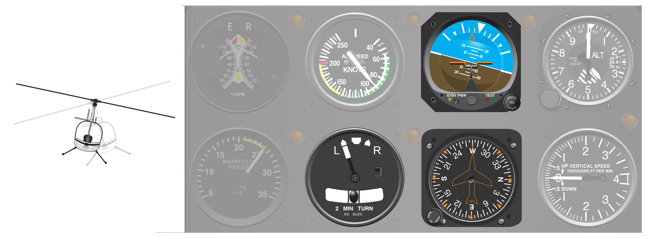
The bank attitude of a helicopter is the angular relation of its lateral axis to the natural horizon. To maintain a straight course in visual flight, keep the lateral axis of the helicopter level with the natural horizon. Assuming the helicopter is in coordinated flight, any deviation from a laterally level attitude produces a turn. [Figure 8-4]
Attitude Indicator
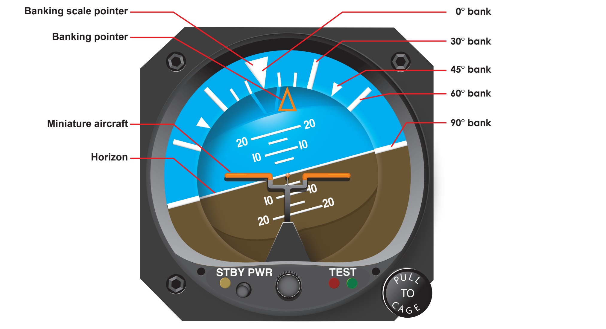
The attitude indicator gives a direct indication of the bank attitude of the helicopter. For instrument flight, the miniature aircraft and the horizon bar of the attitude indicator are substituted for the actual helicopter and the natural horizon. Any change in bank attitude of the helicopter is indicated instantly by the miniature aircraft. For proper interpretation of this instrument, imagine being in the miniature aircraft. If the helicopter is properly trimmed and the rotor tilts, a turn begins. The turn can be stopped by leveling the miniature aircraft with the horizon bar. The ball in the turn-and-slip indicator should always be kept centered through proper pedal trim.
The angle of bank is indicated by the pointer on the banking scale at the top of the instrument. Small bank angles, which may not be seen by observing the miniature aircraft, can easily be determined by referring to the banking scale pointer.
Pitch-and-bank attitudes can be determined simultaneously on the attitude indicator. Even though the miniature aircraft is not level with the horizon bar, pitch attitude can be established by observing the relative position of the miniature aircraft and the horizon bar. [Figure 8-5]
The attitude indicator may show small misrepresentations of bank attitude during maneuvers that involve turns. This precession error can be detected immediately by closely cross-checking the other bank instruments during these maneuvers. Precession is normally noticed when rolling out of a turn. If, upon completion of a turn, the miniature aircraft is level and the helicopter is still turning, make a small change of bank attitude to center the turn needle and stop the movement of the heading indicator.
Heading Indicator
In coordinated flight, the heading indicator gives an indirect indication of a helicopter’s bank attitude. When a helicopter is banked, it turns. When the lateral axis of a helicopter is level, it flies straight. Therefore, in coordinated flight when the heading indicator shows a constant heading, the helicopter is level laterally. A deviation from the desired heading indicates a bank in the direction the helicopter is turning. A small angle of bank is indicated by a slow change of heading; a large angle of bank is indicated by a rapid change of heading. If a turn is noticed, apply opposite cyclic until the heading indicator indicates the desired heading, simultaneously ensuring the ball is centered. When making the correction to the desired heading, do not use a bank angle greater than that required to achieve a standard rate turn. In addition, if the number of degrees of change is small, limit the bank angle to the number of degrees to be turned. Bank angles greater than these require more skill and precision in attaining the desired results. During straight-and-level flight, the heading indicator is the primary reference for bank control.
Turn Indicator
During coordinated flight, the needle of the turn-and-slip indicator gives an indirect indication of the bank attitude of the helicopter. When the needle is displaced from the vertical position, the helicopter is turning in the direction of the displacement. Thus, if the needle is displaced to the left, the helicopter is turning left. Bringing the needle back to the vertical position with the cyclic produces straight flight. A close observation of the needle is necessary to accurately interpret small deviations from the desired position.