
Chapter 9
Navigation Systems
Very High Frequency Omnidirectional Range (VOR)
VOR is the primary navigational aid (NAVAID) used by civil aviation in the National Airspace System (NAS). The VOR ground station is oriented to magnetic north and transmits azimuth information to the aircraft, providing 360 courses TO or FROM the VOR station. When DME is installed with the VOR, it is referred to as a VOR/DME and provides both azimuth and distance information. When military tactical air navigation (TACAN) equipment is installed with the VOR, it is known as a VORTAC and provides both azimuth and distance information.
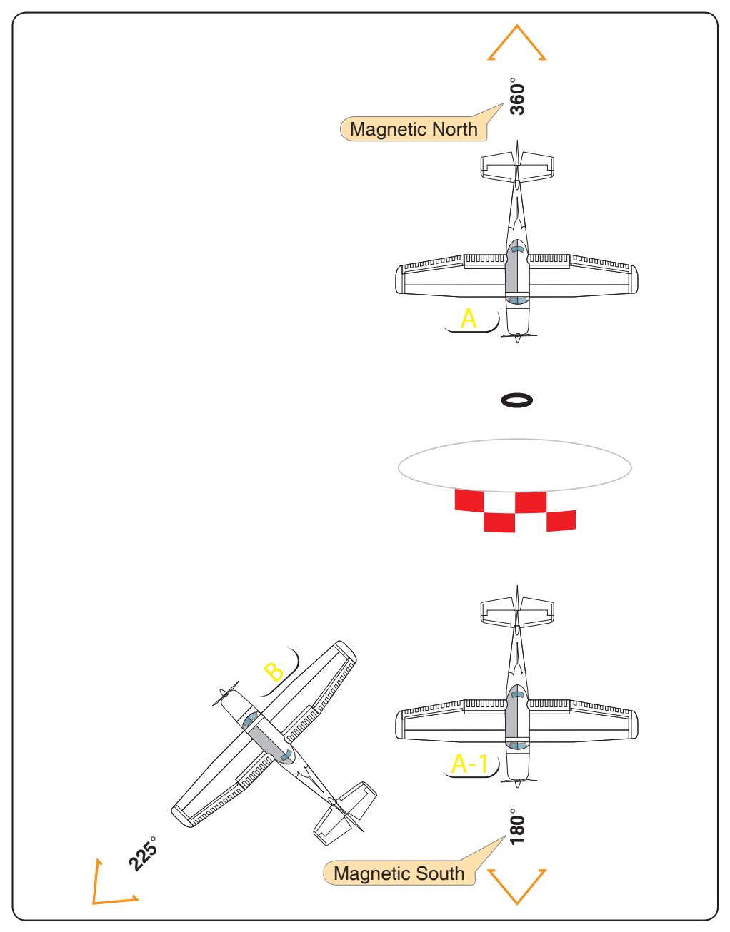
The courses oriented FROM the station are called radials. The VOR information received by an aircraft is not influenced by aircraft attitude or heading. [Figure 9-10] Radials can be envisioned to be like the spokes of a wheel on which the aircraft is on one specific radial at any time. For example, aircraft A (heading 180°) is inbound on the 360° radial; after crossing the station, the aircraft is outbound on the 180° radial at A1. Aircraft B is shown crossing the 225° radial. Similarly, at any point around the station, an aircraft can be located somewhere on a specific VOR radial. Additionally, a VOR needle on an RMI always points to the course that takes you to the VOR station where conversely the ADF needle points to the station as a RB from the aircraft. In the example above, the ADF needle at position A would be pointed straight ahead, at A1 to the aircraft’s 180° position (tail) and at B to the aircraft’s right.
The VOR receiver measures and presents information to indicate bearing TO or FROM the station. In addition to the navigation signals transmitted by the VOR, a Morse code signal is transmitted concurrently to identify the facility, as well as voice transmissions for communication and relay of weather and other information.
VORs are classified according to their operational uses. The standard VOR facility has a power output of approximately 200 watts, with a maximum usable range depending upon the aircraft altitude, class of facility, location of the facility, terrain conditions within the usable area of the facility, and other factors. Above and beyond certain altitude and distance limits, signal interference from other VOR facilities and a weak signal make it unreliable. Coverage is typically at least 40 miles at normal minimum instrument flight rules (IFR) altitudes. VORs with accuracy problems in parts of their service volume are listed in Notices to Airmen (NOTAMs) and in the Airport/Facility Directory (A/FD) under the name of the NAVAID.
VOR Components
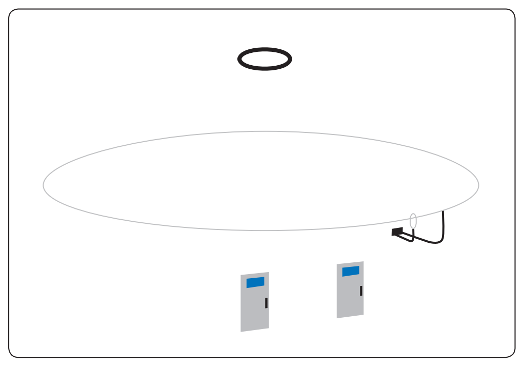
The ground equipment consists of a VOR ground station, which is a small, low building topped with a flat white disc, upon which are located the VOR antennas and a fiberglass cone-shaped tower. [Figure 9-11] The station includes an automatic monitoring system. The monitor automatically turns off defective equipment and turns on the standby transmitter. Generally, the accuracy of the signal from the ground station is within 1°.
VOR facilities are aurally identified by Morse code, or voice, or both. The VOR can be used for ground-to-air communication without interference with the navigation signal. VOR facilities operate within the 108.0 to 117.95 MHz frequency band and assignment between 108.0 and 112.0 MHz is in even-tenth increments to preclude any conflict with ILS localizer frequency assignment, which uses the odd tenths in this range.
The airborne equipment includes an antenna, a receiver, and the indicator instrument. The receiver has a frequency knob to select any of the frequencies between 108.0 to 117.95 MHz. The ON/OFF/volume control turns on the navigation receiver and controls the audio volume. The volume has no effect on the operation of the receiver. You should listen to the station identifier before relying on the instrument for navigation.
VOR indicator instruments have at least the essential components shown in the instrument illustrated in Figure 9-12.
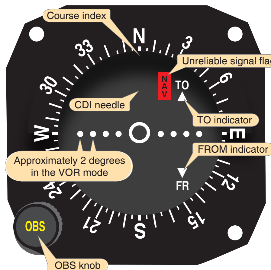
Omnibearing Selector (OBS)
The desired course is selected by turning the omnibearing selector (OBS) knob until the course is aligned with the course index mark or displayed in the course window.
Course Deviation Indicator (CDI)
The course deviation indicator (CDI) is composed of an instrument face and a needle hinged to move laterally across the instrument face. The needle centers when the aircraft is on the selected radial or its reciprocal. Full needle deflection from the center position to either side of the dial indicates the aircraft is 10° or more off course, assuming normal needle sensitivity. The outer edge of the center circle is 2° off course; with each dot representing an additional 2°.