
Chapter 9
Navigation Systems
Area Navigation (RNAV)
Area navigation (RNAV) equipment includes VOR/DME, LORAN, GPS, and inertial navigation systems (INS). RNAV equipment is capable of computing the aircraft position, actual track, groundspeed, and then presenting meaningful information to the pilot. This information may be in the form of distance, cross-track error, and time estimates relative to the selected track or WP. In addition, the RNAV equipment installations must be approved for use under IFR. The Pilot’s Operating Handbook/Airplane Flight Manual (POH/AFM) should always be consulted to determine what equipment is installed, the operations that are approved, and the details of equipment use. Some aircraft may have equipment that allows input from more than one RNAV source, thereby providing a very accurate and reliable navigation source.
VOR/DME RNAV
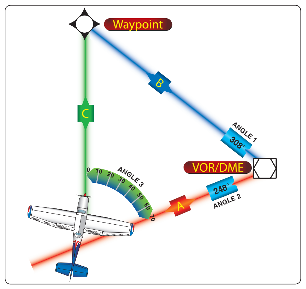
VOR RNAV is based on information generated by the present VORTAC or VOR/DME system to create a WP using an airborne computer. As shown in Figure 9-22, the value of side A is the measured DME distance to the VOR/DME. Side B, the distance from the VOR/DME to the WP, and angle 1 (VOR radial or the bearing from the VORTAC to the WP) are values set in the flight deck control. The bearing from the VOR/DME to the aircraft, angle 2, is measured by the VOR receiver. The airborne computer continuously compares angles 1 and 2 and determines angle 3 and side C, which is the distance in NMs and magnetic course from the aircraft to the WP. This is presented as guidance information on the flight deck display.
VOR/DME RNAV Components
Although RNAV flight deck instrument displays vary among manufacturers, most are connected to the aircraft CDI with a switch or knob to select VOR or RNAV guidance. There is usually a light or indicator to inform the pilot whether VOR or RNAV is selected. [Figure 9-23] The display includes the WP, frequency, mode in use, WP radial and distance, DME distance, groundspeed, and time to station.
Most VOR/DME RNAV systems have the following airborne controls:
- OFF/ON/Volume control to select the frequency of the VOR/DME station to be used.
- MODE select switch used to select VOR/DME mode, with:
- Angular course width deviation (standard VOR operation); or
- Linear cross-track deviation as standard (±5 NM full scale CDI).
- RNAV mode, with direct to WP with linear cross-track deviation of ±5 NM.
- RNAV/APPR (approach mode) with linear deviation of ±1.25 NM as full scale CDI deflection.
- WP select control. Some units allow the storage of more than one WP; this control allows selection of any WP in storage.
- Data input controls. These controls allow user input of WP number or ident, VOR or LOC frequency, WP radial and distance.
While DME groundspeed readout is accurate only when tracking directly to or from the station in VOR/DME mode, in RNAV mode the DME groundspeed readout is accurate on any track.
Function of VOR/DME RNAV
The advantages of the VOR/DME RNAV system stem from the ability of the airborne computer to locate a WP wherever it is convenient, as long as the aircraft is within reception range of both nearby VOR and DME facilities. A series of these WPs make up an RNAV route. In addition to the published routes, a random RNAV route may be flown under IFR if it is approved by air traffic control (ATC). RNAV DPs and standard terminal arrival routes (STARs) are contained in the DP and STAR booklets.
VOR/DME RNAV approach procedure charts are also available. Note in the VOR/DME RNAV chart excerpt shown in Figure 9-24 that the WP identification boxes contain the following information: WP name, coordinates, frequency, identifier, radial distance (facility to WP), and reference facility elevation. The initial approach fix (IAF), final approach fix (FAF), and missed approach point (MAP) are labeled.