
Chapter 9
Navigation Systems
DME Arc
There are many instrument approach procedures (IAPs) that incorporate DME arcs. The procedures and techniques given here for intercepting and maintaining such arcs are applicable to any facility that provides DME information. Such a facility may or may not be collocated with the facility that provides final approach guidance.
As an example of flying a DME arc, refer to Figure 9-17 and follow these steps:
- Track inbound on the OKT 325° radial, frequently checking the DME mileage readout.
- A 0.5 NM lead is satisfactory for groundspeeds of 150 knots or less; start the turn to the arc at 10.5 miles. At higher groundspeeds, use a proportionately greater lead.
- Continue the turn for approximately 90°. The roll-out heading is 055° in a no wind condition.
- During the last part of the intercepting turn, monitor the DME closely. If the arc is being overshot (more than 1.0 NM), continue through the originally planned roll-out heading. If the arc is being undershot, roll-out of the turn early.
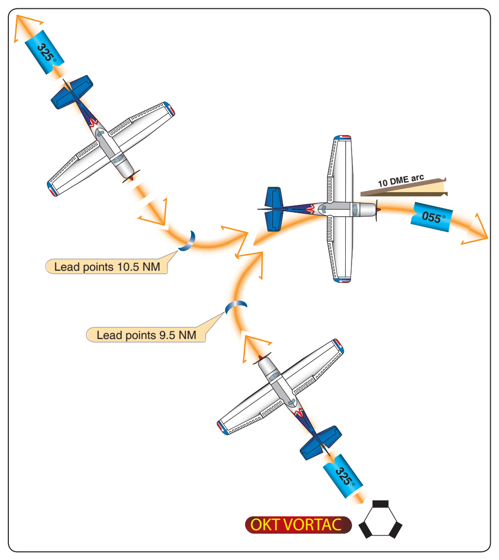
The procedure for intercepting the 10 DME when outbound is basically the same, the lead point being 10 NM minus 0.5 NM or 9.5 NM.
When flying a DME arc with wind, it is important to keep a continuous mental picture of the aircraft’s position relative to the facility. Since the wind-drift correction angle is constantly changing throughout the arc, wind orientation is important. In some cases, wind can be used in returning to the desired track. High airspeeds require more pilot attention because of the higher rate of deviation and correction.
Maintaining the arc is simplified by keeping slightly inside the curve; thus, the arc is turning toward the aircraft and interception may be accomplished by holding a straight course. When outside the curve, the arc is “turning away” and a greater correction is required.
To fly the arc using the VOR CDI, center the CDI needle upon completion of the 90° turn to intercept the arc. The aircraft’s heading is found very near the left or right side (270° or 90° reference points) of the instrument. The readings at that side location on the instrument give primary heading information while on the arc. Adjust the aircraft heading to compensate for wind and to correct for distance to maintain the correct arc distance. Recenter the CDI and note the new primary heading indicated whenever the CDI gets 2°– 4° from center.
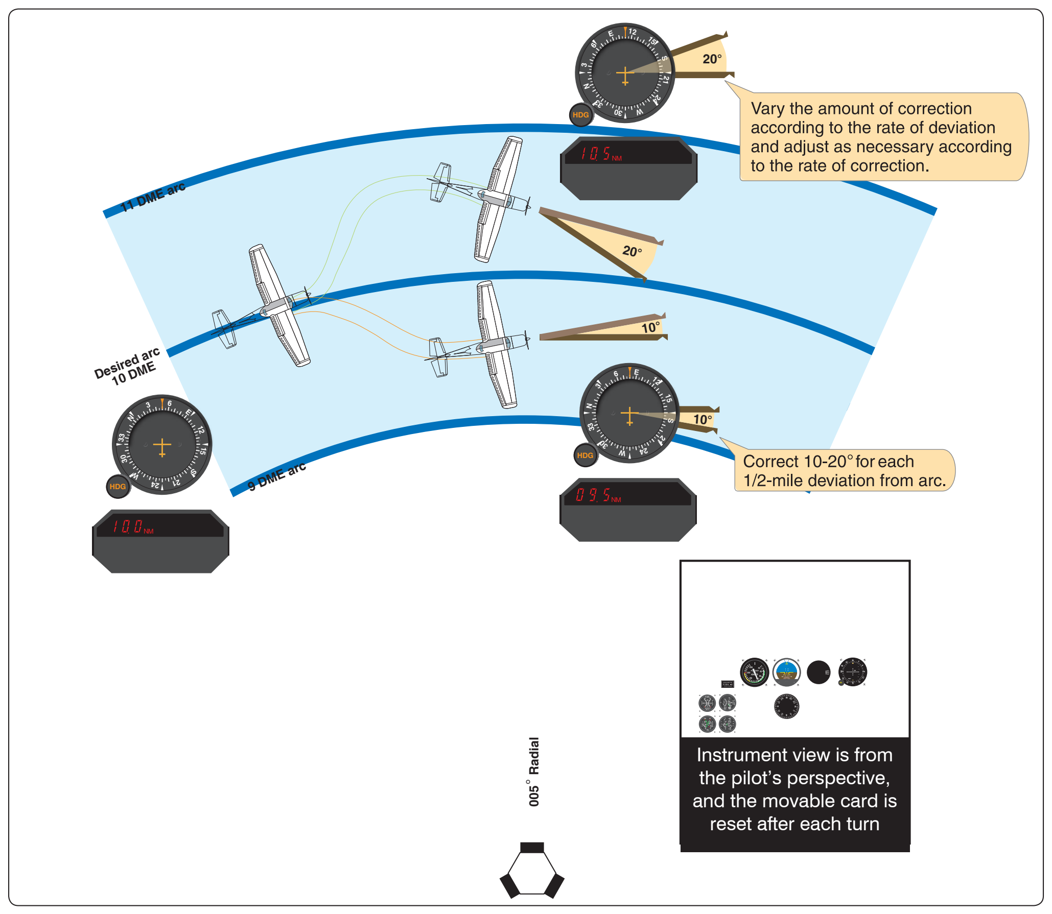
With an RMI, in a no wind condition, pilots should theoretically be able to fly an exact circle around the facility by maintaining an RB of 90° or 270°. In actual practice, a series of short legs are flown. To maintain the arc in Figure 9-18, proceed as follows:
- With the RMI bearing pointer on the wingtip reference (90° or 270° position) and the aircraft at the desired DME range, maintain a constant heading and allow the bearing pointer to move 5°– 10° behind the wingtip. This causes the range to increase slightly.
- Turn toward the facility to place the bearing pointer 5°– 10° ahead of the wingtip reference, and then maintain heading until the bearing pointer is again behind the wingtip. Continue this procedure to maintain the approximate arc.
- If a crosswind causes the aircraft to drift away from the facility, turn the aircraft until the bearing pointer is ahead of the wingtip reference. If a crosswind causes the aircraft to drift toward the facility, turn until the bearing is behind the wingtip.
- As a guide in making range corrections, change the RB 10°– 20° for each half-mile deviation from the desired arc. For example, in no-wind conditions, if the aircraft is ½ to 1 mile outside the arc and the bearing pointer is on the wingtip reference, turn the aircraft 20° toward the facility to return to the arc.
Without an RMI, orientation is more difficult since there is no direct azimuth reference. However, the procedure can be flown using the OBS and CDI for azimuth information and the DME for arc distance.
Intercepting Lead Radials
A lead radial is the radial at which the turn from the arc to the inbound course is started. When intercepting a radial from a DME arc, the lead varies with arc radius and groundspeed. For the average general aviation aircraft, flying arcs such as those depicted on most approach charts at speeds of 150 knots or less, the lead is under 5°. There is no difference between intercepting a radial from an arc and intercepting it from a straight course.
With an RMI, the rate of bearing movement should be monitored closely while flying the arc. Set the course of the radial to be intercepted as soon as possible and determine the approximate lead. Upon reaching this point, start the intercepting turn. Without an RMI, the technique for radial interception is the same except for azimuth information, which is available only from the OBS and CDI.
The technique for intercepting a localizer from a DME arc is similar to intercepting a radial. At the depicted lead radial (LR 223 or LR 212 in Figures 9-19, 9-20, and 9-21), a pilot having a single VOR/LOC receiver should set it to the localizer frequency. If the pilot has dual VOR/LOC receivers, one unit may be used to provide azimuth information and the other set to the localizer frequency. Since these lead radials provide 7° of lead, a half-standard rate turn should be used until the LOC needle starts to move toward center.
DME Errors
A DME/DME fix (a location based on two DME lines of position from two DME stations) provides a more accurate aircraft location than using a VOR and a DME fix.
DME signals are line-of-sight; the mileage readout is the straight line distance from the aircraft to the DME ground facility and is commonly referred to as slant range distance. Slant range refers to the distance from the aircraft’s antenna to the ground station (A line at an angle to the ground transmitter. GPS systems provide distance as the horizontal measurement from the WP to the aircraft. Therefore, at 3,000 feet and 0.5 miles the DME (slant range) would read 0.6 NM while the GPS distance would show the actual horizontal distance of.5 DME. This error is smallest at low altitudes and/or at long ranges. It is greatest when the aircraft is closer to the facility, at which time the DME receiver displays altitude (in NM) above the facility. Slant range error is negligible if the aircraft is one mile or more from the ground facility for each 1,000 feet of altitude above the elevation of the facility.