
Chapter 4
Approaches
The United States version of the Ground-Based Augmentation System (GBAS) has traditionally been referred to as the Local Area Augmentation System (LAAS). The worldwide community has adopted GBAS as the official term for this type of navigation system. To coincide with international terminology, the FAA is also adopting the term GBAS to be consistent with the international community. GBAS is a ground-based augmentation to GPS that focuses its service on the airport area (approximately a 20–30 mile radius) for precision approach, DPs, and terminal area operations. It broadcasts its correction message via a very high frequency (VHF) radio data link from a ground-based transmitter. GBAS yields the extremely high accuracy, availability, and integrity necessary for Category I, II, and III precision approachesand provides the ability for flexible, curved approach paths. GBAS demonstrated accuracy is less than one meter in both the horizontal and vertical axis. [Figure 4-13] The GBAS augments the GPS to improve aircraft safety during airport approaches and landings. It is expected that the end state configuration will pinpoint the aircraft’s position to within one meter or less with a significant improvement in service flexibility and user operating costs.
GBAS is comprised of ground equipment and avionics. The ground equipment includes four reference receivers, a GBAS ground facility, and a VHF data broadcast transmitter. This ground equipment is complemented by GBAS avionics installed on the aircraft. Signals from GPS satellites are received by the GBAS GPS reference receivers (four receivers for each GBAS) at the GBAS equipped airport. The reference receivers calculate their position using GPS. The GPS reference receivers and GBAS ground facility work together to measure errors in GPS provided position.
The GBAS ground facility produces a GBAS correction message based on the difference between actual and GPS calculated position. Included in this message is suitable integrity parameters and approach path information. This GBAS correction message is then sent to a VHF data broadcast (VDB) transmitter. The VDB broadcasts the GBAS signal throughout the GBAS coverage area to avionics in GBAS equipped aircraft. GBAS provides its service to a local area (approximately a 20–30 mile radius). The signal coverage is designed support the aircraft’s transition from en route airspace into and throughout the terminal area airspace.
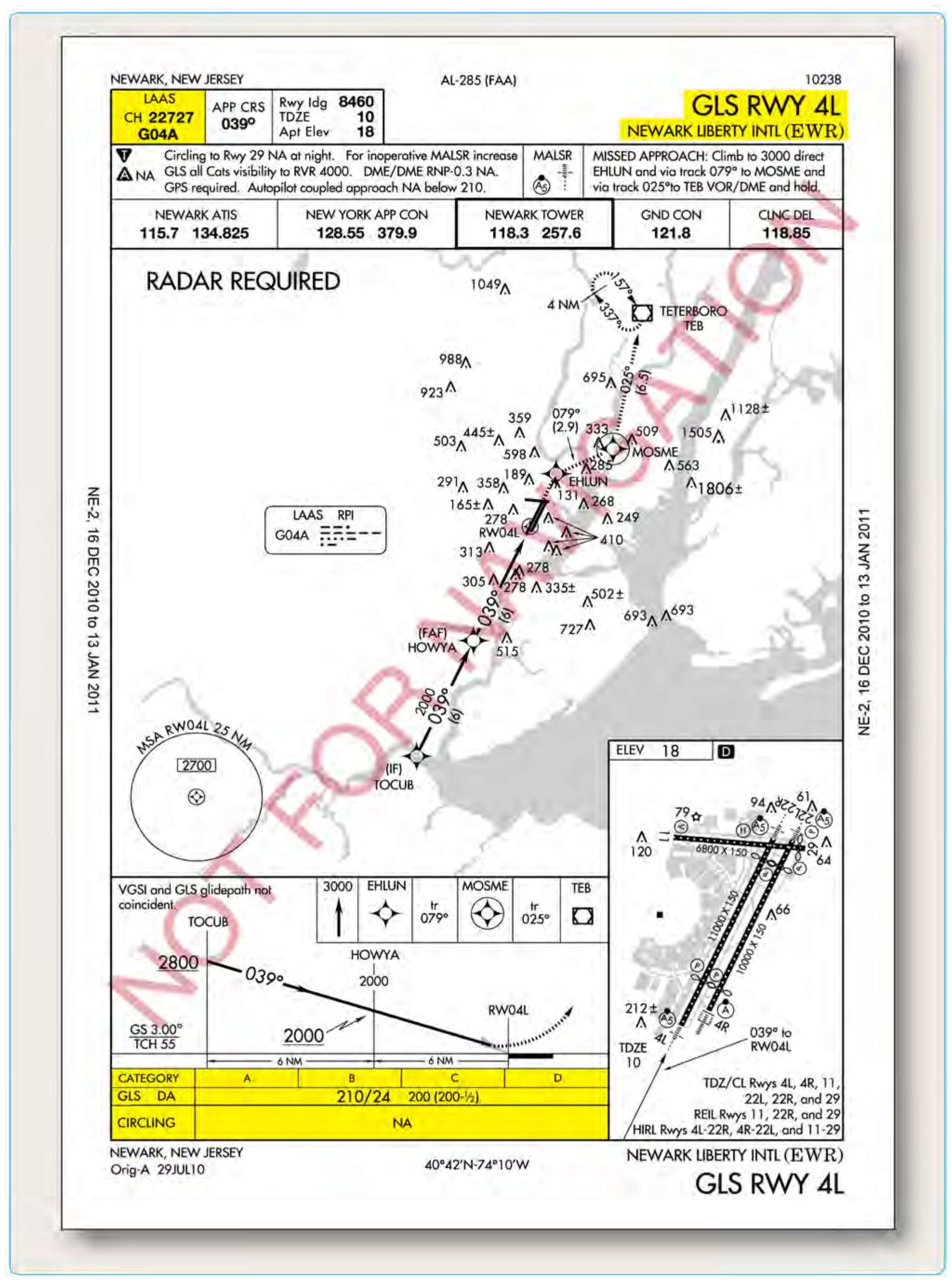
The GBAS equipment in the aircraft uses the corrections provided on position, velocity, and time to guide the aircraft safely to the runway. This signal provides ILS look alike guidance as low as 200 feet above touchdown. GBAS will eventually support landings all the way to the runway surface. Figure 4-14 is an example of a GBAS (LAAS) approach into Newark, New Jersey.
Required Navigation Performance (RNP)
The operational advantages of RNP include accuracy, onboard performance monitoring and alerting which provide increased navigation precision and lower minimums than conventional RNAV. RNP DAs can be as low as 250 feet with visibilities as low as 3/4 SM. Besides lower minimums, the benefits of RNP include improved obstacle clearance limits, as well as reduced pilot workload. When RNP capable aircraft fly an accurate, repeatable path, ATC can be confident that these aircraft are at a specific position, thus maximizing safety and increasing capacity.
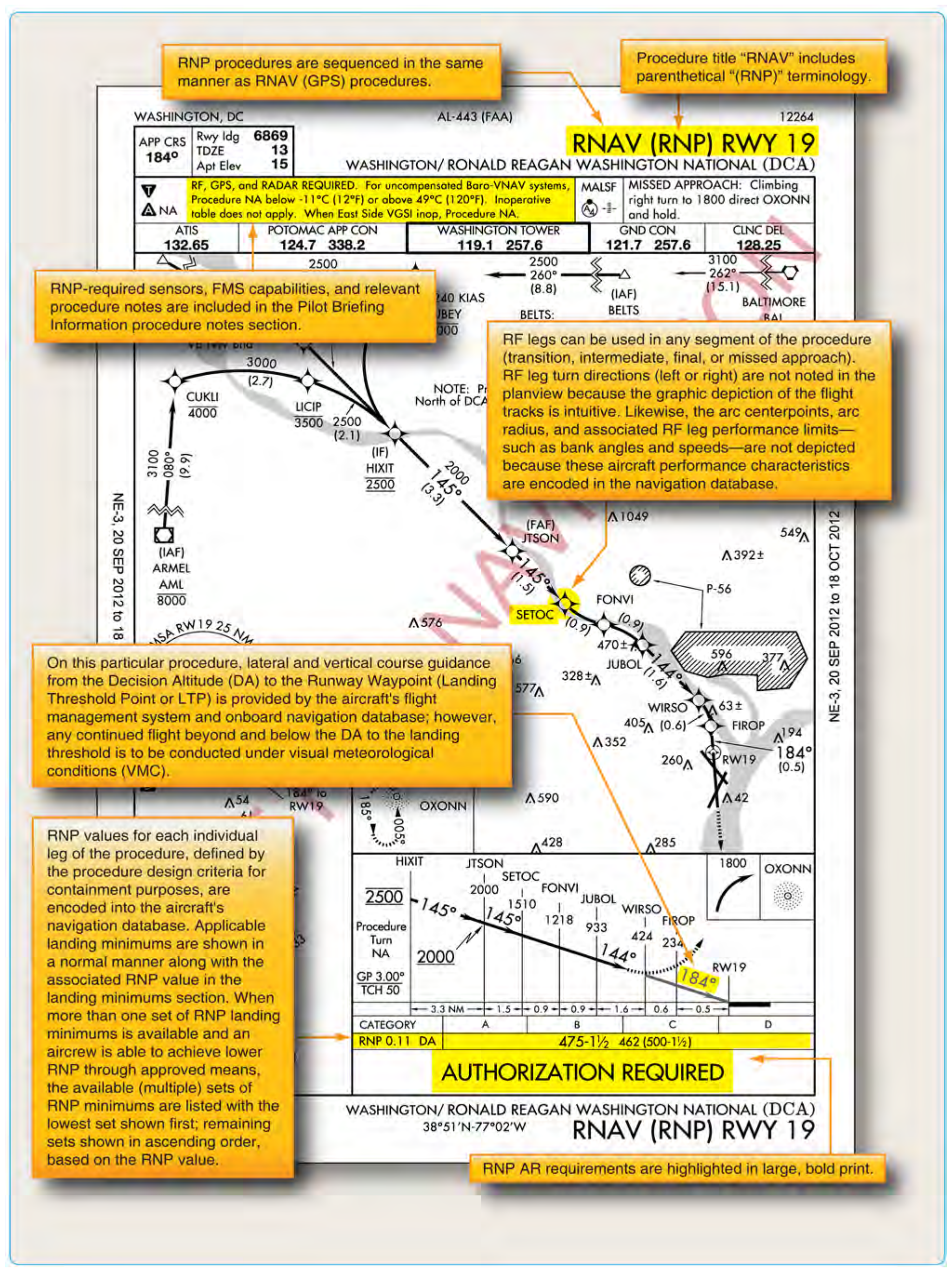
To attain the benefits of RNP approach procedures, a key component is curved flight tracks. Constant radius turns around a fix are called “radius-to-fix legs (RF legs).” These turns, which are encoded into the navigation database, allow the aircraft to avoid critical areas of terrain or conflicting airspace while preserving positional accuracy by maintaining precise, positive course guidance along the curved track. The introduction of RF legs into the design of terminal RNAV procedures results in improved use of airspace and allows procedures to be developed to and from runways that are otherwise limited to traditional linear flight paths or, in some cases, not served by an IFR procedure at all. Navigation systems with RF capability are a prerequisite to flying a procedure that includes an RF leg. Refer to the notes box of the pilot briefing portion of the approach chart in Figure 4-15.
In the United States, operators who seek to take advantage of RNP approach procedures must meet the special RNP requirements outlined in FAA AC 90-101, Approval Guidance for RNP Procedures with Authorization Required (AR). Currently, most new transport category airplanes receive an airworthiness approval for RNP operations. However, differences can exist in the level of precision that each system is qualified to meet. Each individual operator is responsible for obtaining the necessary approval and authorization to use these instrument flight procedures with navigation databases.
RNAV Approach Authorization
Like any other authorization given to air carriers and Part 91 operators, the authorization to use VNAV on a conventional non-precision approach, RNAV approaches, or LNAV/VNAV approaches is found in that operator’s OpSpecs, AFM, or other FAA-approved documents. There are many different levels of authorizations when it comes to the use of RNAV approach systems. The type of equipment installed in the aircraft, the redundancy of that equipment, its operational status, the level of flight crew training, and the level of the operator’s FAA authorization are all factors that can affect a pilot’s ability to use VNAV information on an approach.
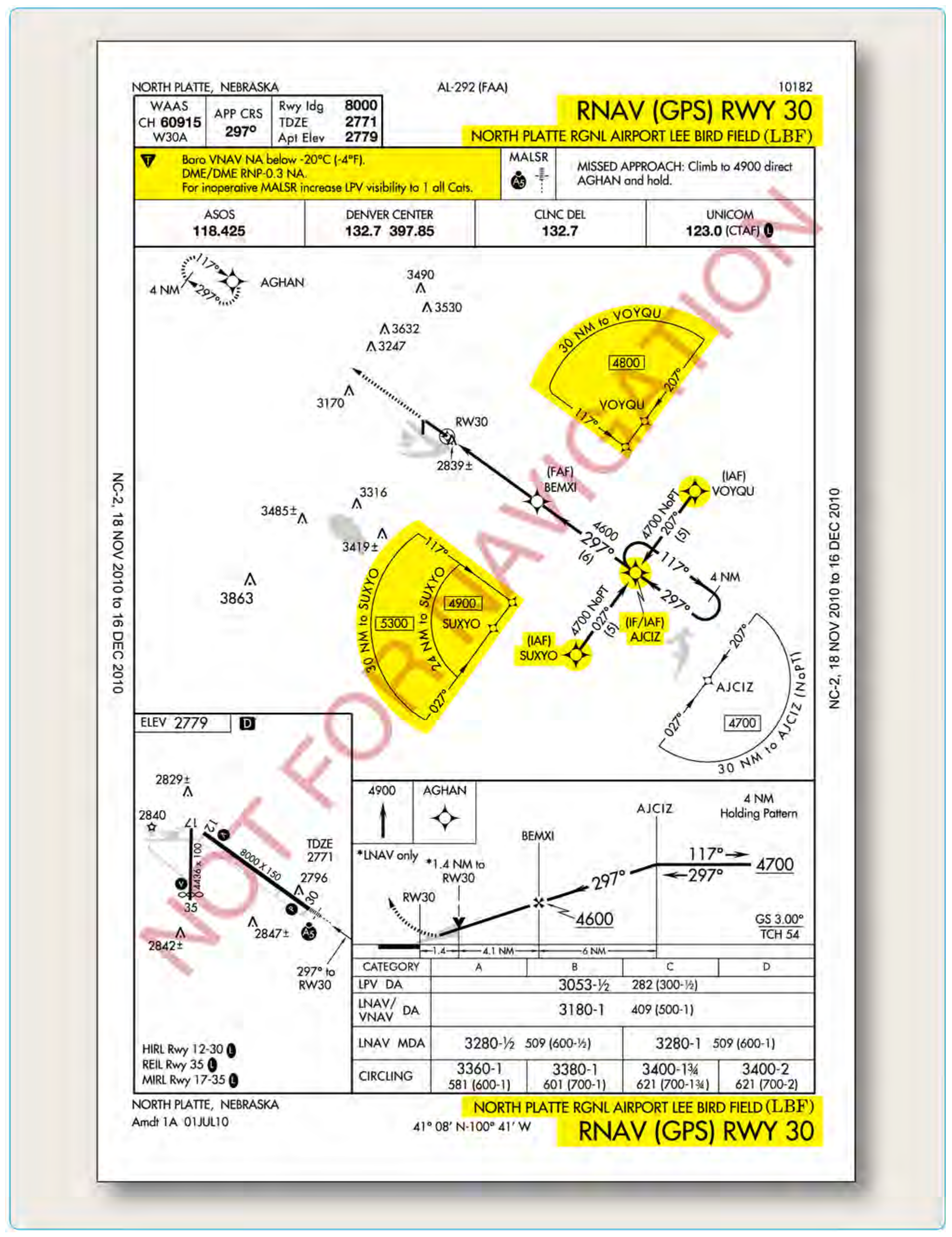
Because most Part 121, 125, 135, and 91 flight departments include RNAV approach information in their pilot training programs, a flight crew considering an approach to North Platte, Nebraska, using the RNAV (GPS) RWY 30 approach shown in Figure 4-16, would already know which minimums they were authorized to use. The company’s OpSpecs, FOM, and the AFM for the pilot’s aircraft would dictate the specific operational conditions and procedures by which this type of approach could be flown.
There are several items of note that are specific to this type of approach that should be considered and briefed. One is the terminal arrival area (TAA) that is displayed in the approach planview. TAAs, discussed later in this chapter, depict the boundaries of specific arrival areas, and the MIA for those areas. The TAAs should be included in an IAP briefing in the same manner as any other IFR transition altitude. It is also important to note that the altitudes listed in the TAAs should be referenced in place of the MSAs on the approach chart for use in emergency situations.
In addition to the obvious differences contained in the planview of Figure 4-16, RNAV (GPS) approach procedure example, pilots should be aware of the issues related to Baro-VNAV and RNP. The notes section of the procedure in the example contains restrictions relating to these topics.
RNP values for each individual leg of the procedure, defined by the procedure design criteria for containment purposes, are encoded into the aircraft’s navigation database. Applicable landing minimums are shown in a normal manner along with the associated RNP value in the landing minimums section.
RNP required sensors, FMS capabilities, and relevant procedure notes are included in the Pilot Briefing Information procedure notes section. [Figure 4-15] RNP AR requirements are highlighted in large, bold print. RNP procedures are sequenced in the same manner as RNAV (GPS) procedures. Procedure title “RNAV” includes parenthetical “(RNP)” terminology. RF legs can be used in any segment of the procedure (transition, intermediate, final, or missed approach). RF leg turn directions (left or right) are not noted in the planview because the graphic depiction of the flight tracks is intuitive. Likewise, the arc center points, arc radius, and associated RF leg performance limits, such as bank angles and speeds are not depicted because these aircraft performance characteristics are encoded in the navigation database. RNP values for each individual leg of the procedure, defined by the procedure design criteria for containment purposes, are encoded into the aircraft's navigation database. Applicable landing minimums are shown in a normal manner along with the associated RNP value in the landing minimums section.
When more than one set of RNP landing minimums is available and an aircrew is able to achieve lower RNP through approved means, the available (multiple) sets of RNP minimums are listed with the lowest set shown first; remaining sets shown in ascending order, based on the RNP value. On this particular procedure, lateral and vertical course guidance from the DA to the Runway Waypoint (LTP) is provided by the aircraft’s FMS and onboard navigation database; however, any continued flight below the DA to the landing threshold is to be conducted under VMC. [Figure 4-15]