
Chapter 2
Design and Construction
These requirements were adhered to for many years. Today, containers achieve the required holding and deployment needs through design tailoring. The bottom corners of the reserve container are designed so that the bag is held in place while the pilot chute and bridle deploy and then releases the bag, rotating it out of the container top to bottom into the airstream. At the same time, the bag can still deploy quickly in the event of a horseshoe-type malfunction.
The main container is less restrictive than the reserve in holding the main canopy in place during deployment. This is important so that there is no tendency for the bag to twist or be unstable on deployment. With many of the main canopies used today, if the bag is unstable, it results in the main canopy opening unevenly and causing spins and possible malfunctions. Along with the main bag, the main risers must be able to deploy evenly for the same reasons.
In the early days of skydiving, the primary body position was a stable, face-to-earth position. This resulted in the main container being behind the parachutist out of the airflow. One of the primary problems faced during those days was the high incidence of pilot chute hesitations. This was the result of poor training and lack of understanding of that air flow. Eventually skydivers learned to sit up during deployment causing the air to flow over their back sweeping the pilot chute into the main stream. Hand deployed pilot chutes were developed to make packing easier and eliminate the need for a metal ripcord.
In the face-to-earth position, the primary purpose of the container is to hold the canopy and pilot chute closed, and then allow it to open during deployment. Today, body positions experienced during free fall range from head-down to feet-to-earth and everything in between. Where speeds formerly experienced ranged from 110 miles per hour (mph) to maybe 140 mph, today speeds in a head-down position can exceed 200 mph. This has changed the container dynamics to ensure a more secure system and increased protection from the wind blast. These changes have resulted in more secure and streamlined configurations to accommodate these new requirements. Figure 2-13 shows a modern container design shaped to meet the high-speed airflows of today.
An additional area that needs to be addressed when designing piggyback systems is the main riser covers. In the early days of sport piggyback designs, the main risers were held in position by webbing keepers. As the sport progressed, the use of fully enclosed main riser covers became the norm. In their attempt to protect the main risers during high-speed free fall, some designs tend to restrict the deployment of the reserve container in the event of a “total” main pack malfunction. When this happens and the main container remains closed, the main riser covers do not open. Because of this, there is additional restriction over the upper corners of the reserve container. This contributes to higher reserve bag release forces. In severe cases, this can result in a reserve pilot chute in tow with potential serious consequences. The balance between sufficient main riser protection and the requirement for unhindered reserve deployment is a critical design feature.

Most modern sport parachute containers have housings of some sort to accommodate ripcords and riser release cables. These flexible metal conduits come in 3 basic types in varying diameters: non-compressible, relaxed, and non-extendable. The housing type is critical to provide proper protection and function for the usage. Non-extendable is used for most ripcord housings, except on Navy seat packs. Relaxed refers to the ripcord housing that is not completely compressible. Non-compressible housing is the correct type to use for 3-ring cutaway systems so the compression does not cause the sides to release unevenly.
Harness Design
According to Poynter’s Parachute Manual, “the harness is an arrangement of cotton, linen, nylon, or Dacron® webbing, which is designed to conform to the shape of the load (usually the body), to be carried in order to secure it properly so that the opening forces and the weight of the load are evenly distributed during opening and descent.”
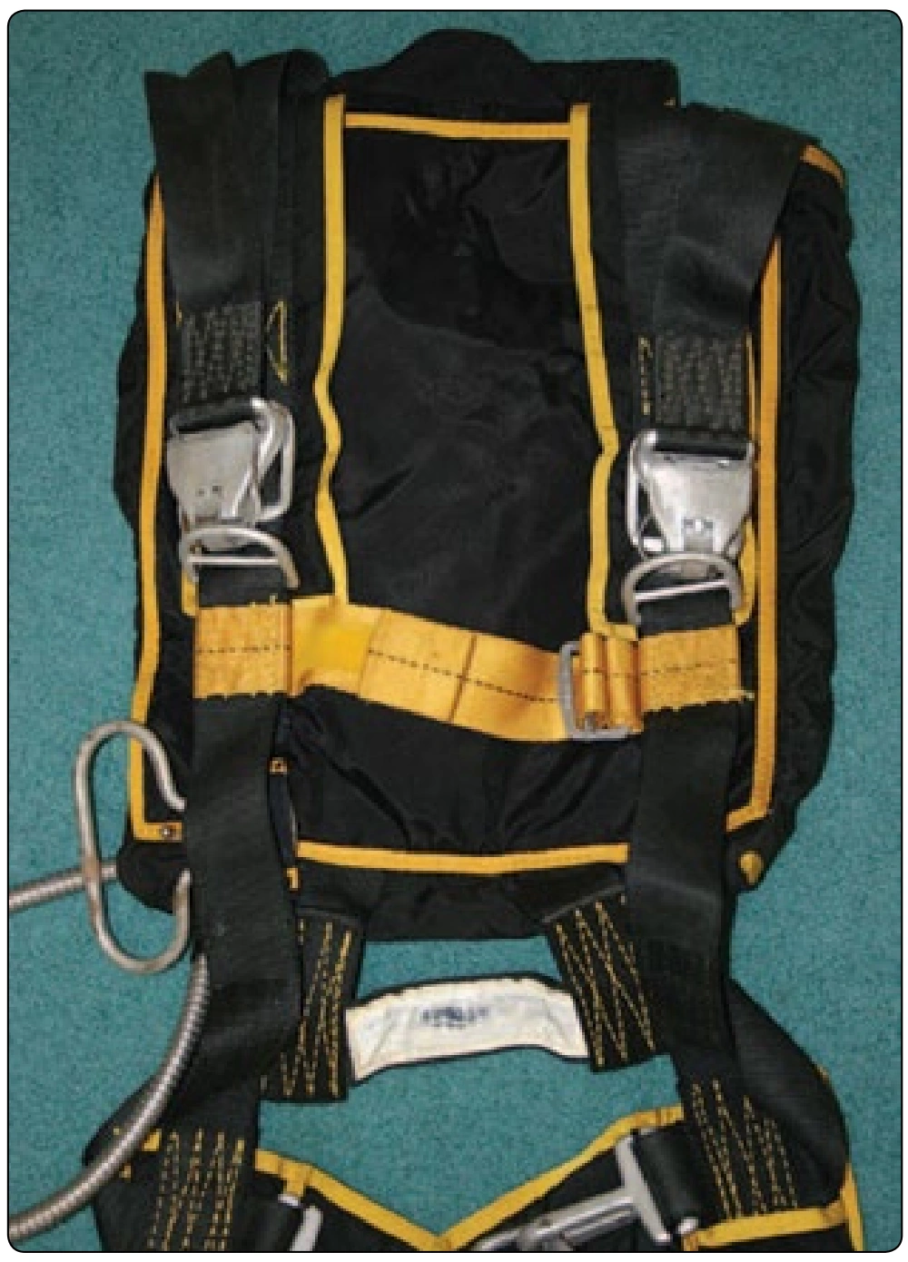
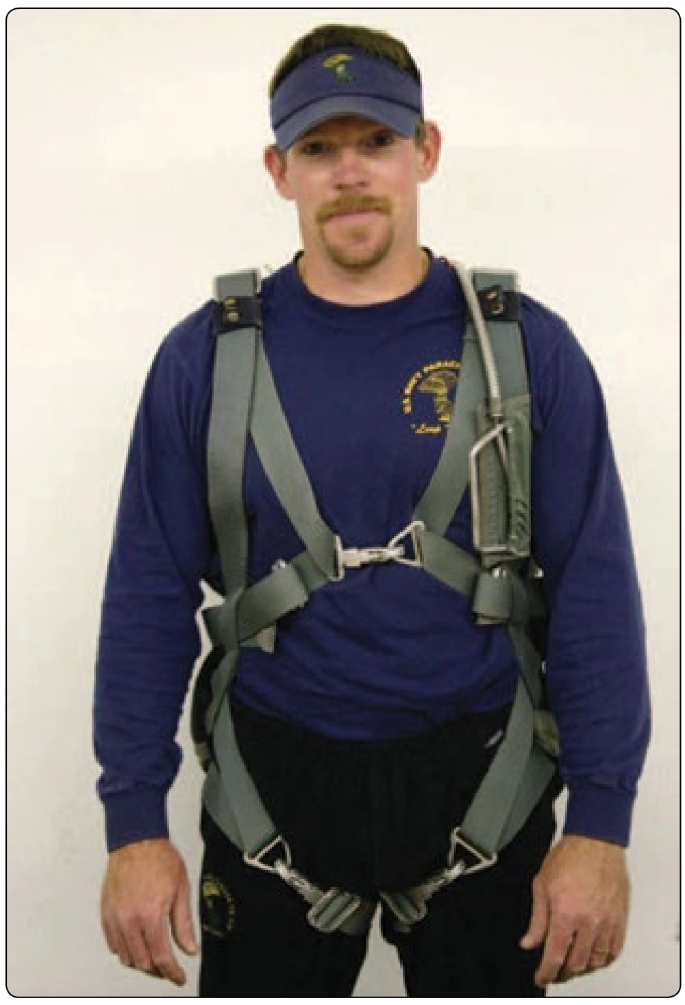
The earliest harness was nothing more than a swing seat that the parachutist sat on and then held onto the risers or suspension straps. It soon became apparent that if the openings were in any way uneven, it could be very precarious for the parachutist. While the sling seat worked for the ride down, it was necessary to add additional straps to secure the parachutist. These straps included the leg, back, and chest straps. The standard harness configuration is equipped to secure a torso, head, arms, and legs with straps. Others have been added over time for additional purposes, such as survival kits or cushions. Figure 2-14 shows a basic military style harness. This harness configuration has seven points of adjustment to allow fitting of most military personnel.
Most of the early parachute systems had the harness detachable from the containers. This allowed interchangeability for various models. In the 1970s, skydiving systems began to integrate the harness into a true harness/container assembly.
This was accomplished by sandwiching the harness between the container and backpad and sewing them together.
Figure 2-15 shows one of the earliest custom systems called the “super swooper.” This harness was the precursor of today’s sport harnesses.
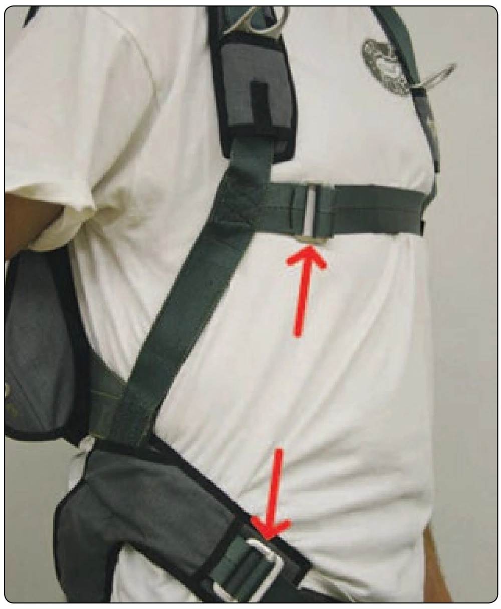
As skydiving and the sport parachute industry has grown, most of the equipment is now custom-built for each individual. The standard piggyback harness configuration of today is a fixed main lift web with adjustments only at the chest and leg straps. [Figure 2-16] Elimination of the extra hardware and webbing has resulted in a dramatic reduction in weight of modern systems. Along with this has been an increase in comfort and flexibility. One of the most innovative designs adopted in recent years is the “articulated” harness. This design incorporates metal rings at the hip junction and the chest-strap attachment. [Figure 2-17] These rings allow a full range of motion both in the air and on the ground and increase the fit and comfort of the harness. Note however that hardware incorporated into the main lift web or junction of a harness should be equal in strength to the webbing or at least the certification of the harness. Type 7 harness webbing is 6,000 pounds tensile. Type 13 harness webbing is 7,000 pounds tensile. The stainless steel “RW-8” is certified to 3,500 pounds. The stainless steel 5010 Harness Ring is certified to 5,000 pounds.
The “stepped” harness is not as strong as the continuous horizontal harness [Figure 2-18]. If point loading occurs on a stepped harness, stitching may break, and the junction can fail with disastrous results. With a continuous horizontal, if all the stitching were to fail, the wearer would still be wrapped in webbing and restrained in the harness.
In recent years and with the increasing popularity of vertical skydiving or “free flying,” greater speeds are experienced with corresponding higher loads on the harnesses. For many years, harnesses were overbuilt as they were basically copies of military designs. As the sport has progressed, equipment has been made lighter and smaller.