Chapter 3
Components and Systems
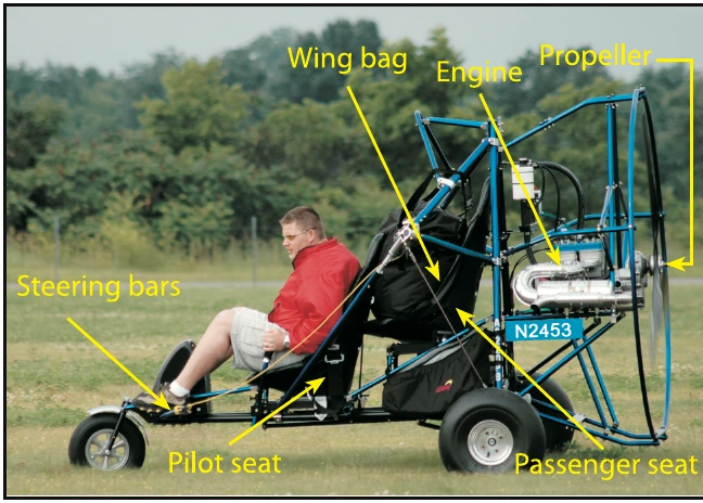
Although powered parachutes come in an array of shapes and sizes, the basic design features are fundamentally the same. All powered parachutes consist of an airframe (referred to as a cart) a propeller powered by an engine, and a ram-air inflated wing. [Figure 3-1]
The Airframe
Most powered parachute airframes are manufactured with aircraft-grade hardware. A few PPC manufacturers are building fiber-composite carts. The airframe’s tubular construction means light weight and ease of replacement if tubes are bent. The airframe includes one or two seats, flight controls, and an instrument panel. The airframe also incorporates the engine, the fuel tank, the propeller and points of attachment for the wing and steering lines.
Although side-by-side configurations exist, in most powered parachutes the pilot and passenger are seated in a tandem (fore and aft) configuration. Dual flight controls are required for training. Not all PPCs have full dual controls; depending on the configuration of the cart and added controls (that are optional from different airframe manufacturers) the flight instructor can adequately control the aircraft during training from the rear seat during takeoff, flight, and landing procedures with dual throttle controls. While in the rear seat, the flight instructor can have positive control of the aircraft at all times by physically pulling on the steering lines and using a dual control throttle. Like airplanes, not all powered parachutes are adequately configured to conduct flight training. The flight instructor with a powered parachute endorsement should determine his or her ability to control each individual PPC from the back seat with the dual controls for training purposes. [Figure 3-2]
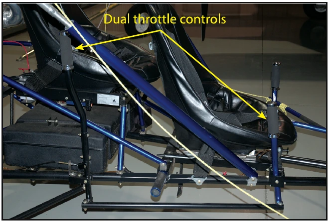
The pilot flies from the front seat in order to reach the steering bars, throttle control, ground steering control and magneto switches, and to keep the CG in balance; you cannot fly alone from the back seat for this reason.
The cart by itself is not very aerodynamic because it does not need to be; it flies at slower airspeeds. However, without the wing attached and inflated to limit speed, the pilot needs to be careful to avoid high speeds, such as when taxiing to and from the hangar for canopy layout. The wheels, their bearings, and the cart suspension were not designed to handle high speeds.
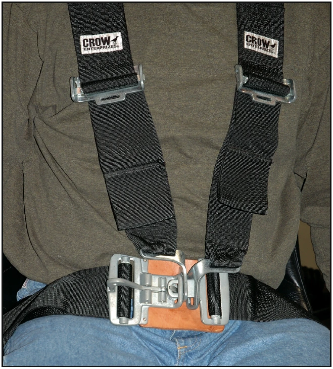
Some manufacturers use an adjustable front seat to allow for the varied length of the pilot’s legs to comfortably reach the steering bars. Powered parachutes can be outfitted with a variety of seatbelts, including a four-point harness system that securely fastens each occupant into their seat. [Figure 3-3]
Most powered parachutes have three wheels, or a tricycle gear configuration, although some have four. Ground steering is typically a steering bar connected to the nosewheel that moves left and right. Some powered parachutes have a tiller device for ground steering. There are a number of ground steering designs that vary between manufacturer, make, and model.
Brakes are an optional piece of equipment on the powered parachute, as the square foot area of the parachute itself provides aerodynamic braking. Pilots should use smooth and controlled operation of the throttle on the ground to maintain safe and controllable ground speeds, particularly when taxiing with the chute inflated. Students should practice throttle control to learn how far the PPC takes to come to a full stop when the power is reduced to idle. However, for runway incursion prevention and general safety, brakes are advised and highly recommended so you can stop when you need to. Never use your feet as a form of braking, as physical injury is probable.
Center of Gravity Adjustments
Each manufacturer has specific procedures in the Pilot’s Operating Handbook (POH) to adjust the CG of the cart, so that the cart is hanging at the proper nose high/nose low position—including the weight position in the cart and the fore/aft position of the wing attachment points.
As discussed in Chapter 2, the attachment points for the wing (parachute) must be adjusted for variations in pilot weight, which affect the center of gravity (CG) location of the cart.
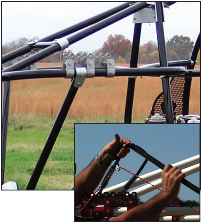
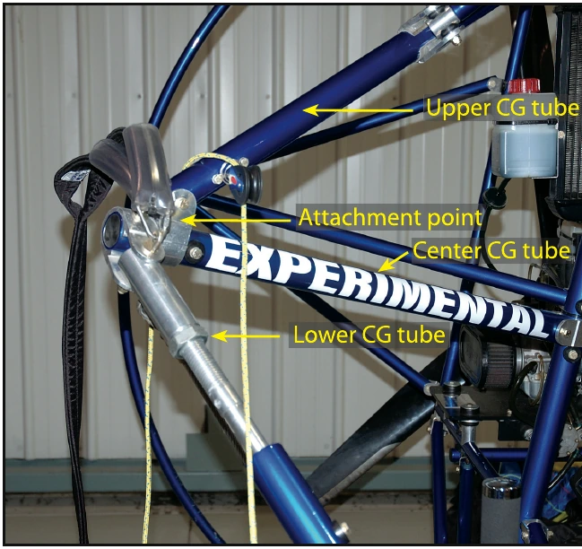
There are typically two types of wing attachment systems: center of gravity adjustment tubes, or a bracket with a number of fore and aft attachment points. Each of these systems performs the same task. Either system adjusts the wing attachment points based on the cart CG. This is primarily based on the weight of the occupant in the front seat, usually the pilot. The rear seat occupant’s weight does not typically come into consideration when determining the CG position of the PPC, as the rear seat is usually positioned very near the cart CG. To maintain the best overall performance, the aircraft needs to fly with a slight nose-up attitude, as specified in the aircraft POH.
Use the POH to determine the proper adjustment for the particular aircraft because there are many configurations and designs that vary by manufacturer, make, and model.