Chapter 3
Components and Systems
The Powerplant
The typical powered parachute engine can be two- or four-stroke, liquid- or air-cooled, 50 to 100 horsepower. Some engines have electric starters and some have pull starters. Most PPC engines have reduction drives that, when attached, reduce the propeller RPM to half to one quarter the engine RPM. [Figure 3-16] The engines are as varied as the powered parachutes they power. Modern technology has allowed the powered parachute engine to become lighter, more efficient and, most importantly, dependable. Chapter 4 covers the powerplant in more detail.
The Propeller
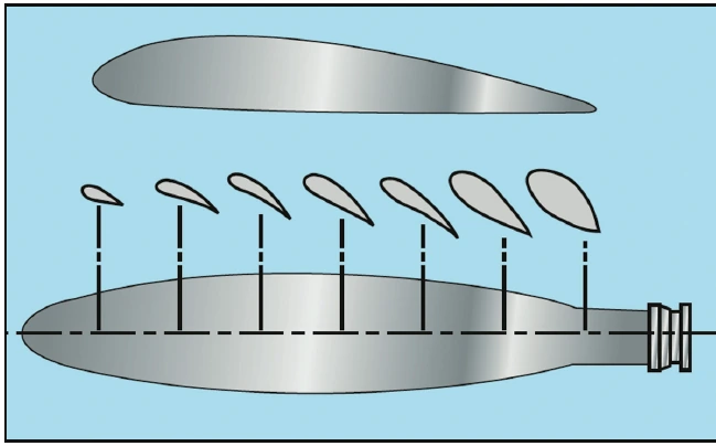
Propellers are “power converters” that change the engine horsepower into “thrust.” Thrust is the force that propels the aircraft through the air by pushing the powered parachute forward. Aerodynamically speaking, a propeller is a rotating airfoil and the same principles that apply to the wing will apply to the propeller. [Figure 3-17] Engine power is transferred to the propeller through a rotating crankshaft that turns the propeller through the air, producing thrust in the same way as wings produce lift. The shape of the blade creates thrust vectors because it is cambered like the airfoil of a wing. Consequently, as the air flows past the propeller, the pressure on one side is less than that on the other. As in a wing, this produces a reaction force in the direction of the lower pressure. In the case of the propeller, which is mounted in a vertical plane, the area of decreased pressure is in front of the propeller, and the force (thrust) is in a forward direction. Aerodynamically, the thrust is the result of the propeller shape and the angle of attack of the blade.
The typical powered parachute has a ground adjustable propeller. The adjustment of the propeller should only be conducted to meet the engine manufacturer’s maximum recommended RPM target. Pilots who are not familiar with adjusting the propeller and how it will affect the PPC performance should consult with a knowledgeable source prior to making any propeller adjustments.
The engine mount is designed by individual manufacturers for each cart configuration. The majority of the total aircraft weight is determined by the engine and mounting configuration. When trailering the PPC over bumpy terrain or over long trips, the bouncing of the cart in the trailer can put extreme stress on this mounting system. In addition, repeated hard landings of the cart can also stress the welds of the engine mount. Consistent detailed inspections of the engine mount should be an important part of every preflight and post-flight inspection.
Just like an airplane propeller, the powered parachute propeller turns at such great speeds that it becomes invisible when in motion. The dangers of a turning propeller require every pilot to maintain the highest level of safety and respect for the consequences of body parts, pets, and debris coming in contact with a rotating propeller. Always treat the propeller as if the ignition were on. Debris on the takeoff/landing field is a danger to the propeller as well as to the people who may be in the prop-wash area behind the propeller. Stones, small pieces of metal, and sticks can become dangerous projectiles if kicked into the propeller during takeoff and landing. Just as with any airframe or wing component of a powered parachute, if the propeller becomes damaged, nicked or dinged, the aircraft’s performance can be greatly affected.
Some pilots elect to use tape or rock deflector guards to protect the leading edge from rock/debris damage. Regardless, taking proper care of the PPC propeller is as critical as proper engine and wing care.
Axle and Wheel Assembly
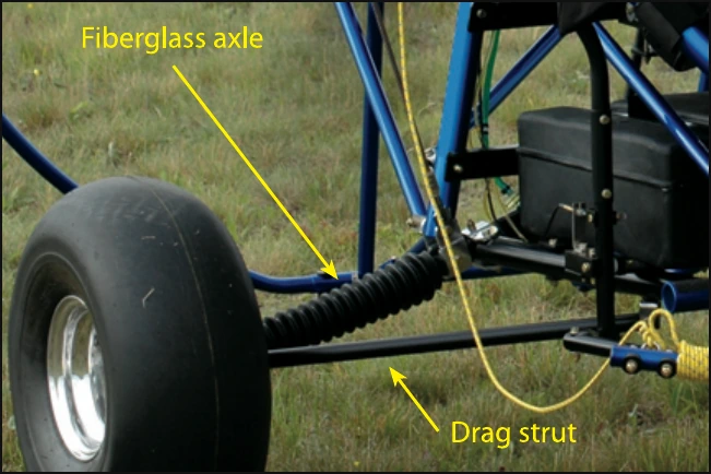
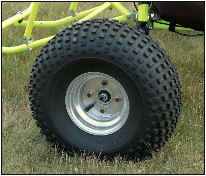
The rear and front wheels of the powered parachute are an assembly and consist of a tire, a rim, and an inner and outer set of wheel bearings. The wheel is secured on a spindle and held in place by a nut and a cotter pin. Each spindle is typically mounted on a suspension system which provides elasticity and at the same time is very strong. [Figure 3-18] The suspension system varies by manufacturer from one cart to another; refer to the POH for exact configuration and components. Some powered parachute tires are heavily treaded while others are smooth; pilot preference and the terrain type are determining factors in choice of tire profiles. [Figure 3-19] Tire sealant or thorn guards can be used to minimize flat tires.