Chapter 3
Components and Systems
Powered parachutes are typically equipped with a 12 volt direct-current electrical system. A basic powered parachute electrical system consists of a magneto, alternator or generator, battery, master/battery switch, voltage regulator, and associated electrical wiring.
Electrical energy stored in a battery provides a source of electrical power for starting the engine and a limited supply of electrical power for use in the event the alternator or generator fails.
The electrical system is turned on or off with a master switch. Turning the master switch to the ON position provides electrical energy to all the electrical equipment circuits with the exception of the ignition system. Equipment that commonly uses the electrical system for its source of energy includes:
- Position lights.
- Anticollision lights.
- Instrument lights.
- Radio equipment.
- Electronic instrumentation.
- Electric fuel pump.
- Starting motor.
Fuses or circuit breakers are used in the electrical system to protect the circuits and equipment from electrical overload. Spare fuses of the proper amperage limit should be carried in the powered parachute to replace defective or blown fuses. Circuit breakers have the same function as a fuse but can be manually reset, rather than replaced, if an overload condition occurs in the electrical system. Placards at the fuse or circuit breaker panel identify the circuit by name and show the amperage limit.
An ammeter is used to monitor the performance of the electrical system. The ammeter shows if the alternator/generator is producing an adequate supply of electrical power. It also indicates whether or not the battery is receiving an electrical charge.
A voltage meter also provides electrical information as to the battery voltage, an additional status of your electrical system.
A voltage regulator changes the variable output of the magneto or generator to the 12-volt DC level for the battery and the electric system. The voltage output is typically higher than the battery voltage. For example, a 12-volt battery would be fed from the magneto/generator/alternator system through the voltage regulator which produces approximately 13 to 14 volts. This higher voltage keeps the battery charged.
The Steering Bars
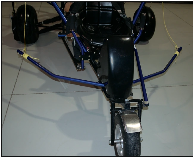
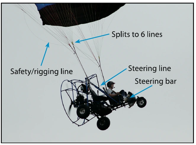
The steering bars are located just aft of the nosewheel and mounted on each side of the aircraft; they move forward and aft when the pilot applies foot pressure. [Figure 3-8] The steering lines from the trailing edge of the wing are attached to the outer ends of the steering bars. (Some manufacturers have developed a steering pedal system on their airframes, although the steering lines function in the same manner.) The main steering lines divide into various smaller lines, which attach to multiple points on the trialing edge of the wing. Pushing on either one of the steering bars causes the steering lines to pull down the corresponding surface of the trailing edge on the wing, creating drag. This in turn slows that side of the wing and banks the PPC into a turn.
Pushing both steering bars simultaneously causes the steering lines to pull down equally on the trailing edge, which causes two things to happen: it decreases the powered parachute’s forward speed by increasing the drag and it changes the shape of the wing, increasing angle of attack which increases lift. This procedure, called “flaring” or “braking the wing” allows the pilot to touch down at a slower rate of speed and descent, thus creating a smoother landing, which results in less wear and tear on the aircraft as a whole. [Figure 3-9]
Wings and Components
The powered parachute wing is unique, as compared to a fabric wing on an airplane, in that when it is not inflated it loses its ability to produce lift. When a powered parachute wing is inflated or pressurized, it becomes semi-rigid and is capable of producing lift and supporting a load. Rather than being bolted to the fuselage like an airplane, the parachute wing is attached to the cart by lines and cables which are known as risers.
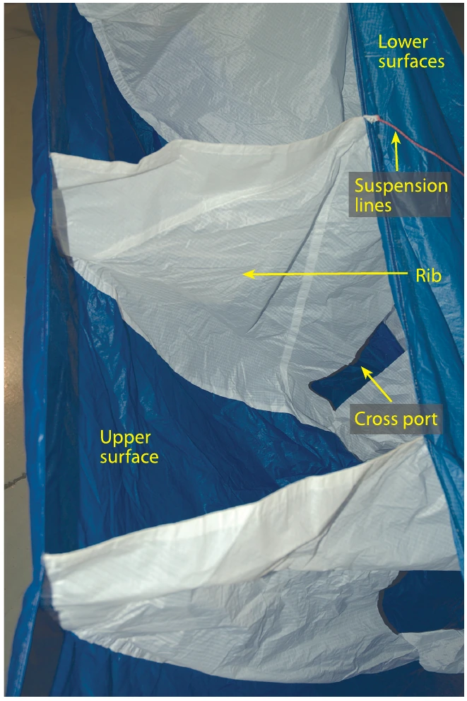
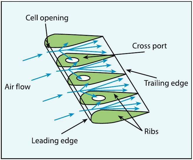
The wings are manufactured by attaching an upper and lower section of skin to ribs. [Figure 3-10] The ribs of the wing determine the airfoil shape. [Figure 3-11] The shape of a powered parachute wing will change slightly when faced with different gross weights, air pressures, and environmental conditions such as moisture, air temperature and wind.
Different wing manufacturers use different fabric treatments to render the fabric airtight, so the air that enters the wing cannot escape through the fabric surface. The top surface of the wing is generally treated to help protect it from ultraviolet light and the elements. Keeping the powered parachute wing out of direct sunlight will increase its useful life.
If the fabric degrades and air is allowed to escape through pores of the cloth, the overall flight performance of the wing is greatly reduced. If your powered parachute wing should become too porous, more groundspeed may be needed to pressurize the wing, takeoff distance may increase, more RPM may be required to hold altitude, and fuel consumption may increase.