Chapter 3
Components and Systems
At first sight, the suspension lines on the powered parachute wing might appear like an unorganized wad of strings. On the contrary, each line has a distinct purpose and each line has distinct properties. The suspension lines are sometimes designated A through D and differ between manufacturers; check your POH to know the line labels for your PPC. [Figure 3-12] The front suspension lines are located at the leading edge and the steering lines connect to the trailing edge. The suspension lines come together at a point where they connect with the riser. (The risers are the connection between the suspension lines and the cart.) Many manufacturers color-code the wing suspension lines to assist the pilot in their preflight inspection and layout of the wing prior to inflation. [Figure 3-12]
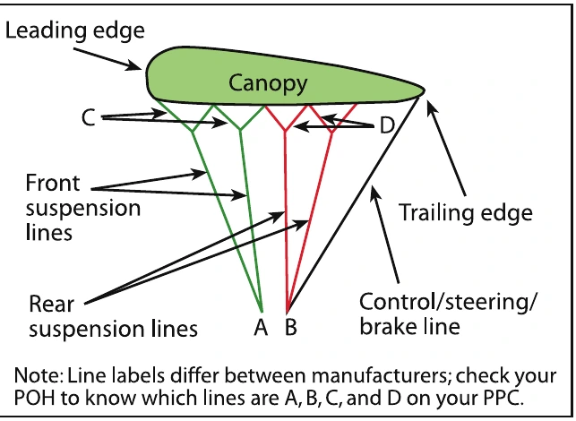
Suspension lines must be constructed of very strong materials, yet remain very small in profile to reduce parasite drag. The most commonly used materials are polyaramid and polyethelene, which are both carbon based.
Kevlar® is a common polyaramid used for suspension lines. Its properties render it extremely strong, as well as resistant to stretching or shrinking, and it is not susceptible to temperature changes. However, one critical drawback of polyaramids is that they tend to kink or knot when looped around. When polyaramids are used to construct suspension lines, they are encased in a skin of a terylene product, like Dacron® or a product with similar properties. Polyethelene materials, such as Spectra®, Dyneema® or Technora®, are very strong as well as more flexible than polyaramids, which makes them more durable under hard use. However, polyethelene materials are more likely to stretch or shrink, and they are more susceptible to temperature changes. If your wing is equipped with polyethelene suspension lines, it is imperative you do not store your equipment in a place that might experience extreme temperatures. The POH or owner manual provided by the chute manufacturer will specify limits for temperature and storage.
Every line on the powered parachute wing is precisely measured and fitted to a specific location. Therefore, it is imperative to inspect the wing during preflight, in addition to having the wing and its lines inspected periodically by qualified technicians. The technician will conduct strength tests as well as look for wear and compromised attachment points; refer to your wing manufacturer’s specifications for inspection parameters. Under no circumstances should powered parachute suspension lines be spliced or tied if severed! Each line’s length and strength is specifically calibrated. If you tie a knot in the line you will change the specifically-engineered flight characteristics of the wing, rendering it unairworthy.
Risers
Also known as “V lines,” the risers are the intermediate link between the suspension lines and the airframe or the attachment point of the wing to the airframe.
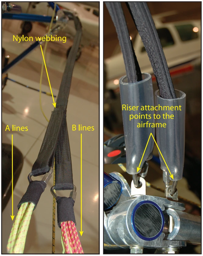
The risers are generally constructed of webbing, which takes on the appearance of two straps that incorporate a main cable and a safety cable as one unit. [Figure 3-13] Some of the older designs of wings may have braided wire cables serving as their risers. The risers are connected to the suspension lines and to the aircraft with various connections such as with D-rings and eyebolts.
During flight, as discussed in Chapter 2, propeller-driven aircraft are affected by the rotation of engine components and the propeller. This is commonly referred to as the “left turning tendency,” which includes torque and sometimes P factor. There are several design features that have been incorporated into airplanes to counteract the left turning tendency from a clockwise turning propeller. Powered parachute designers can counteract the turning effect by changing the length of the riser cables on one side of the airframe. By decreasing the length of the right riser cable, the wing is given a slight right turn, just enough to cancel the effects of torque at cruise thrust settings. This design feature of the powered parachute wing risers makes it imperative not to mistakenly attach the different length riser cables on the wrong side of the airframe. Remember: the left main and the left safety cables, from the pilot’s seat, are longer than the right main and the right safety cables. Mixing the right and the left cables will result in a pronounced left turn; especially during takeoff when the engine is at full throttle, which could jeopardize the safety of all concerned.
Engine installations with a counterclockwise rotating propeller require opposite adjustments. It is important to know which direction the propeller turns for your PPC to accurately counter turning tendencies.
Alternately, the wing could have the same length risers, and the cart could have a higher attachment point for the left riser. This is why each wing is designed for each cart and should not be interchanged: the wing and the cart is a complete system.
The Fuel Tank
The powered parachute is usually equipped with fuel tanks ranging in capacity from 5 to 20 gallons. As with any aircraft, knowing how much fuel your fuel tank holds is crucial to flight operations. The light-sport aircraft powered parachute has no limitations as to the size of the fuel tank, unlike its ultralight vehicle predecessor. Most PPC powerplants require auto fuel mid-grade or higher to be burned (see the powerplant operating handbook for specific engine specifications).
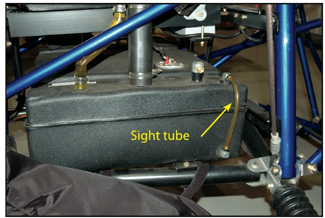
Generally, the fuel tank is located close to the center of gravity, so fuel burn does not affect the balance of the aircraft. Some fuel tanks are clear for visual inspection of the amount of fuel on board while others are dark. Dark tanks or hidden tanks generally have a sight tube to assist the pilot in determining the actual amount of fuel. [Figure 3-14] Some powered parachute manufacturers offer optional fuel level probes and instrument panel analog gauges or incorporate this information into the EIS. As fuel is used by the engine, air needs to enter the tank and take its place; otherwise a vacuum will form inside the fuel tank preventing the fuel pump from drawing fuel. This is usually accomplished with a fuel venting system. This can be a vent in the fuel cap or some other means that vents elsewhere, providing the ability for the fuel tank to breathe. Any vent system must be free of debris or it will cause fuel starvation in flight. This is especially true when a small hole is in the fuel cap that can be easily plugged. Check the fuel venting system during each preflight inspection.
The fuel shut-off valve can be located anywhere in the fuel line. It is important to make sure the fuel valve is open and stays open for normal operation. Most designs have a fuel tank sump drain valve to remove water and solid contaminants. Each design is different and the PPC POH will specify how to conduct this check.
Throttle System
The throttle is the pilot’s hand control to regulate the power provided by the engine. The configuration of the throttle control varies from one cart manufacturer to another. Refer to the POH of each individual PPC for function reference. [Figure 3-15]