
Chapter 4
Powerplants
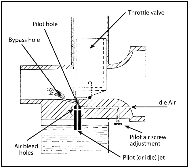
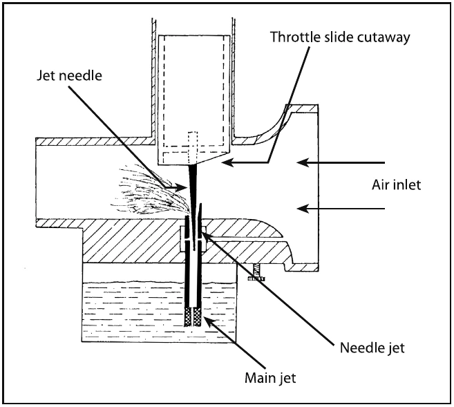
As the throttle is advanced and the throttle valve is raised, the fuel is sucked up through the main jet but is controlled by the opening and taper of the jet needle and needle jet. This is effective throughout most of the mid range operation. About half throttle, the main jet size starts to influence the amount of fuel mixed with the air and this effect continues until it is the main influence at the highest throttle settings. [Figure 4-8]
Two-Stroke Carburetor Jetting
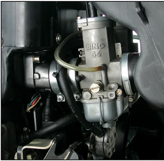
Carburetors are normally set at sea-level pressure, with the jets and settings determined by the manufacturer. [Figure 4-9] However, as altitude increases, the density of air entering the carburetor decreases, while the density of the fuel remains the same. This creates a progressively richer mixture, same fuel but less air, which can result in engine roughness and an appreciable loss of power. The roughness is usually due to spark plug fouling from excessive carbon buildup on the plugs. Carbon buildup occurs because the excessively rich mixture lowers the temperature inside the cylinder, inhibiting complete combustion of the fuel. This condition may occur at high-elevation airports and during climbs or cruise flight at high altitudes. To maintain the correct fuel-air mixture, you can change the main jets and the midrange jets setting for base operations at a high density altitude airport. Operating from low altitude airports and climbing to altitude where the mixture becomes rich for short periods is OK.
Operating an aircraft at a lower altitude airport with the jets set for higher altitudes will create too lean of a mixture, heat up the engine, and cause the engine to seize. The pilot must be aware of the jetting for the machine to adjust the mixture. Consult your POH for specific procedures for setting jets at different altitudes.
Four-Stroke Mixture Settings
Four-stroke engines typically have automatic mixture control for higher altitudes or a mixture control that can be operated by the pilot.
Carburetor Icing
One disadvantage of the carburetor system versus the fuel injected system is its icing tendency. Carburetor ice occurs due to the effect of fuel vaporization and the decrease in air pressure in the venturi, which causes a sharp temperature drop in the carburetor. If water vapor in the air condenses when the carburetor temperature is at or below freezing, ice may form on internal surfaces of the carburetor, including the throttle valve.
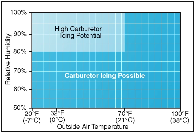
Ice generally forms in the vicinity of the venturi throat. This restricts the flow of the fuel-air mixture and reduces power. If enough ice builds up, the engine may cease to operate. Carburetor ice is most likely to occur when temperatures are below 70°F (21°C) and the relative humidity is above 80 percent. However, due to the sudden cooling that takes place in the carburetor, icing can occur even with temperatures as high as 100°F (38°C) and humidity as low as 50 percent. This temperature drop can be as much as 60 to 70°F. Therefore, at an outside air temperature of 100°F, a temperature drop of 70°F results in an air temperature in the carburetor of 30°F. [Figure 4-10] The first indication of carburetor icing in a powered parachute is a decrease in engine RPM, which may be followed by engine roughness. Although carburetor ice can occur during any phase of flight, it is particularly dangerous when using reduced power during a descent. Under certain conditions, carburetor ice could build unnoticed until you try to add power. To combat the effects of carburetor ice, some engines have a carb heat option. Some of the newer four-stroke engines have carburetor heat turned on all the time to combat icing. Two-stroke engines are typically less susceptible to icing but specific installations dictate how susceptible the carburetor is to icing. Consult the aircraft POH for the probability of carb ice for the specific installation you have and for carb ice procedures.
Fuel Injection Systems
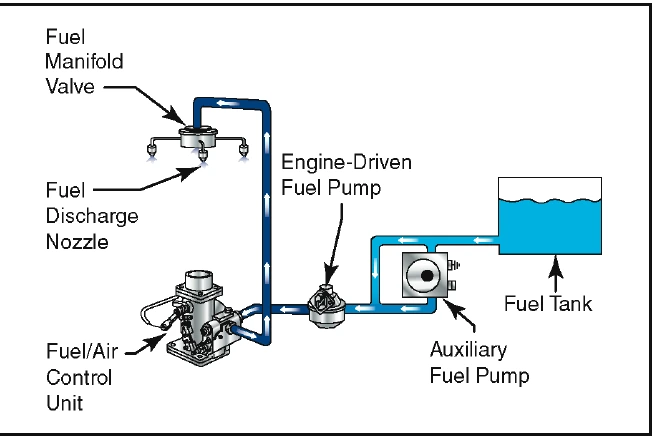
In a fuel injection system, the fuel is injected either directly into the cylinders, or just ahead of the intake valve. A fuel injection system usually incorporates these basic components: an engine-driven fuel pump, a fuel-air control unit, fuel manifold (fuel distributor), discharge nozzles, an auxiliary fuel pump, and fuel pressure/flow indicators. [Figure 4-11]
The auxiliary fuel pump provides fuel under pressure to the fuel-air control unit for engine starting and/or emergency use. After starting, the engine-driven fuel pump provides fuel under pressure from the fuel tank to the fuel-air control unit. This control unit, which essentially replaces the carburetor, meters the fuel and sends it to the fuel manifold valve at a rate controlled by the throttle. After reaching the fuel manifold valve, the fuel is distributed to the individual fuel discharge nozzles. The discharge nozzles, which are located in each cylinder head, inject the fuel-air mixture directly into each cylinder intake port.
Some of the advantages of fuel injection are:
- No carburetor icing.
- Better fuel flow.
- Faster throttle response.
- Precise control of mixture.
- Better fuel distribution.
- Easier cold weather starts.
Disadvantages include: