Chapter 1
Introduction to the Helicopter
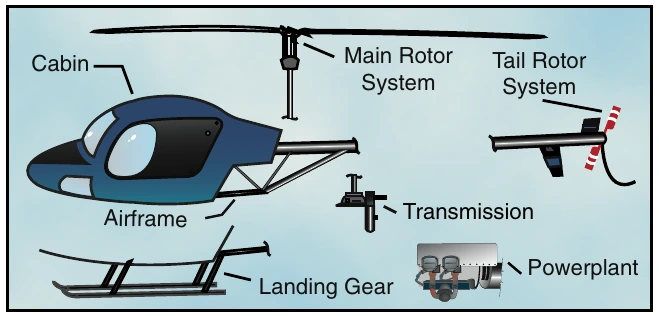
Helicopters come in many sizes and shapes, but most share the same major components. These components include a cabin where the payload and crew are carried; an airframe, which houses the various components, or where components are attached; a powerplant or engine; and a transmission, which, among other things, takes the power from the engine and transmits it to the main rotor, which provides the aerodynamic forces that make the helicopter fly. Then, to keep the helicopter from turning due to torque, there must be some type of antitorque system. Finally there is the landing gear, which could be skids, wheels, skis, or floats. This chapter is an introduction to these components. [Figure 1-1]
The Main Rotor System
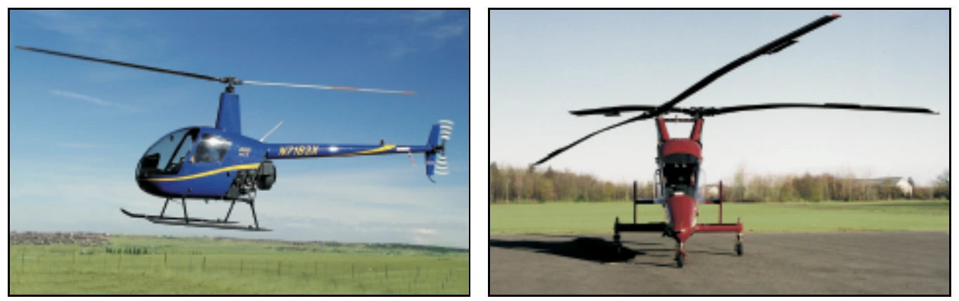
The rotor system found on helicopters can consist of a single main rotor or dual rotors. With most dual rotors, the rotors turn in opposite directions so the torque from one rotor is opposed by the torque of the other. This cancels the turning tendencies. [Figure 1-2]
In general, a rotor system can be classified as either fully articulated, semirigid, or rigid. There are variations and combinations of these systems, which will be discussed in greater detail in Chapter 5—Helicopter Systems.
Fully Articulated Rotor System
A fully articulated rotor system usually consists of three or more rotor blades. The blades are allowed to flap, feather, and lead or lag independently of each other. Each rotor blade is attached to the rotor hub by a horizontal hinge, called the flapping hinge, which permits the blades to flap up and down. Each blade can move up and down independently of the others. The flapping hinge may be located at varying distances from the rotor hub, and there may be more than one.
The position is chosen by each manufacturer, primarily with regard to stability and control.
Payload— The term used for passengers, baggage, and cargo.
Torque— In helicopters with a single, main rotor system, the tendency of the helicopter to turn in the opposite direction of the main rotor rotation.
Blade Flap— The upward or downward movement of the rotor blades during rotation.
Blade Feather or Feathering— The rotation of the blade around the spanwise (pitch change) axis.
Blade Lead or Lag— The fore and aft movement of the blade in the plane of rotation. It is sometimes called hunting or dragging.
Each rotor blade is also attached to the hub by a vertical hinge, called a drag or lag hinge, that permits each blade, independently of the others, to move back and forth in the plane of the rotor disc. Dampers are normally incorporated in the design of this type of rotor system to prevent excessive motion about the drag hinge. The purpose of the drag hinge and dampers is to absorb the acceleration and deceleration of the rotor blades.
The blades of a fully articulated rotor can also be feathered, or rotated about their spanwise axis. To put it more simply, feathering means the changing of the pitch angle of the rotor blades.
Semirigid Rotor System
A semirigid rotor system allows for two different movements, flapping and feathering. This system is normally comprised of two blades, which are rigidly attached to the rotor hub. The hub is then attached to the rotor mast by a trunnion bearing or teetering hinge.
This allows the blades to see-saw or flap together. As one blade flaps down, the other flaps up. Feathering is accomplished by the feathering hinge, which changes the pitch angle of the blade.