
Chapter 12
Attitude Instrument Flying
Heading Indicator
The heading indicator, which is sometimes referred to as a directional gyro (DG), senses movement around the vertical axis and provides a more accurate heading reference compared to a magnetic compass, which has a number of turning errors. [Figure 12-6].
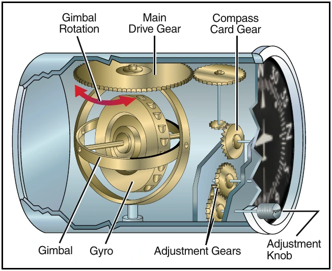
Due to internal friction within the gyroscope, precession is common in heading indicators. Precession causes the selected heading to drift from the set value.
Some heading indicators receive a magnetic north reference from a remote source and generally need no adjustment. Heading indicators that do not have this automatic north-seeking capability are often called “free” gyros, and require that you periodically adjust them. You should align the heading indicator with the magnetic compass before flight and check it at 15minute intervals during flight. When you do an in-flight alignment, be certain you are in straight-and-level, unaccelerated flight, with the magnetic compass showing a steady indication.
Turn Indicators
Turn indicators show the direction and the rate of turn.
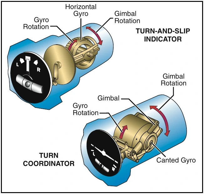
A standard rate turn is 3° per second, and at this rate you will complete a 360° turn in two minutes. A half-standard rate turn is 1.5° per second. Two types of indicators are used to display this information. The turn-and-slip indicator uses a needle to indicate direction and turn rate. When the needle is aligned with the white markings, called the turn index, you are in a standard rate turn. A half-standard rate turn is indicated when the needle is halfway between the indexes.
The turn-and-slip indicator does not indicate roll rate.
The turn coordinator is similar to the turn-and-slip indicator, but the gyro is canted, which allows it to sense roll rate in addition to rate of turn. The turn coordinator uses a miniature aircraft to indicate direction, as well as the turn and roll rate. [Figure 12-7]
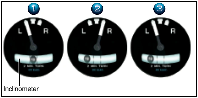
Another part of both the turn coordinator and the turn-and-slip indicator is the inclinometer. The position of the ball defines whether the turn is coordinated or not.
The helicopter is either slipping or skidding anytime the ball is not centered, and usually requires an adjustment of the antitorque pedals or angle of bank to correct it. [Figure 12-8]
Instrument Check
During your preflight, check to see that the inclinometer is full of fluid and has no air bubbles. The ball should also be resting at its lowest point. Since almost all gyroscopic instruments installed in a helicopter are electrically driven, check to see that the power indicators are displaying off indications.
Turn the master switch on and listen to the gyros spool up. There should be no abnormal sounds, such as a grinding sound, and the power out indicator flags should not be displayed. After engine start and before liftoff, set the direction indicator to the magnetic compass. During hover turns, check the heading indicator for proper operation and ensure that it has not precessed significantly. The turn indicator should also indicate a turn in the correct direction. During takeoff, check the attitude indicator for proper indication and recheck it during the first turn.
Magnetic Compass
In some helicopters, the magnetic compass is the only direction seeking instrument. Although the compass appears to move, it is actually mounted in such a way that the helicopter turns about the compass card as the card maintains its alignment with magnetic north.