
Chapter 16
Aerodynamics of the Gyroplane
Helicopters and gyroplanes both achieve lift through the use of airfoils, and, therefore, many of the basic aerodynamic principles governing the production of lift apply to both aircraft. These concepts are explained in depth in Chapter 2—General Aerodynamics, and constitute the foundation for discussing the aerodynamics of a gyroplane.
Autorotation
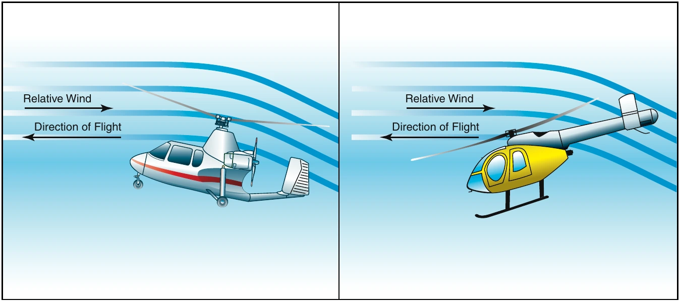
A fundamental difference between helicopters and gyroplanes is that in powered flight, a gyroplane rotor system operates in autorotation. This means the rotor spins freely as a result of air flowing up through the blades, rather than using engine power to turn the blades and draw air from above. [Figure 16-1] Forces are created during autorotation that keep the rotor blades turning, as well as creating lift to keep the aircraft aloft. Aerodynamically, the rotor system of a gyroplane in normal flight operates like a helicopter rotor during an engine-out forward autorotative descent.
Vertical Autorotation
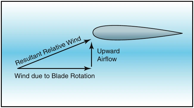
During a vertical autorotation, two basic components contribute to the relative wind striking the rotor blades.
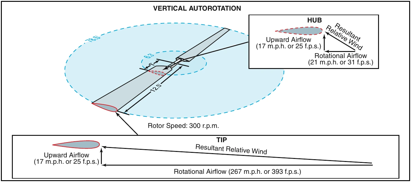
[Figure 16-2] One component, the upward flow of air through the rotor system, remains relatively constant for a given flight condition. The other component is the rotational airflow, which is the wind velocity across the blades as they spin. This component varies significantly based upon how far from the rotor hub it is measured. For example, consider a rotor disc that is 25 feet in diameter operating at 300 r.p.m. At a point one foot outboard from the rotor hub, the blades are traveling in a circle with a circumference of 6.3 feet. This equates to 31.4 feet per second (f.p.s.), or a rotational blade speed of 21 m.p.h. At the blade tips, the circumference of the circle increases to 78.5 feet. At the same operating speed of 300 r.p.m., this creates a blade tip speed of 393 feet per second, or 267 m.p.h. The result is a higher total relative wind, striking the blades at a lower angle of attack. [Figure 16-3]
Rotor Disc Regions
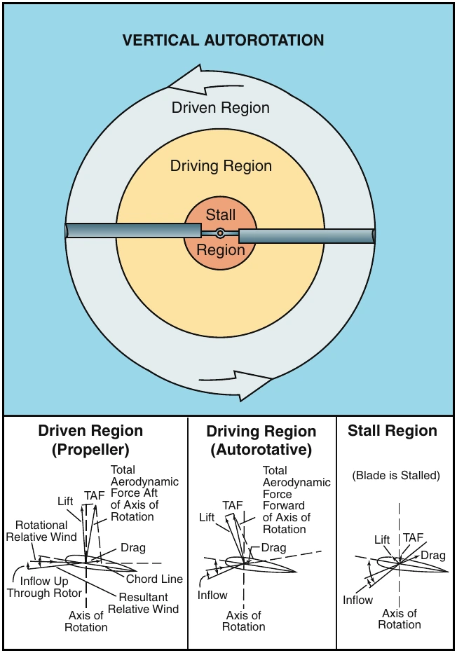
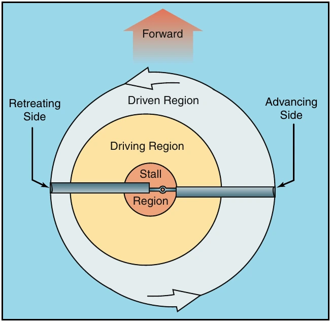
As with any airfoil, the lift that is created by rotor blades is perpendicular to the relative wind. Because the relative wind on rotor blades in autorotation shifts from a high angle of attack inboard to a lower angle of attack outboard, the lift generated has a higher forward component closer to the hub and a higher vertical component toward the blade tips. This creates distinct regions of the rotor disc that create the forces necessary for flight in autorotation. [Figure 16-4] The autorotative region, or driving region, creates a total aerodynamic force with a forward component that exceeds all rearward drag forces and keeps the blades spinning. The propeller region, or driven region, generates a total aerodynamic force with a higher vertical component that allows the gyroplane to remain aloft.
Near the center of the rotor disc is a stall region where the rotational component of the relative wind is so low that the resulting angle of attack is beyond the stall limit of the airfoil. The stall region creates drag against the direction of rotation that must be overcome by the forward acting forces generated by the driving region.
Autorotation in Forward Flight
As discussed thus far, the aerodynamics of autorotation apply to a gyroplane in a vertical descent. Because gyroplanes are normally operated in forward flight, the component of relative wind striking the rotor blades as a result of forward speed must also be considered. This component has no effect on the aerodynamic principles that cause the blades to autorotate, but causes a shift in the zones of the rotor disc.
As a gyroplane moves forward through the air, the forward speed of the aircraft is effectively added to the relative wind striking the advancing blade, and subtracted from the relative wind striking the retreating blade. To prevent uneven lifting forces on the two sides of the rotor disc, the advancing blade teeters up, decreasing angle of attack and lift, while the retreating blade teeters down, increasing angle of attack and lift.
(For a complete discussion on dissymmetry of lift, refer to Chapter 3—Aerodynamics of Flight.) The lower angles of attack on the advancing blade cause more of the blade to fall in the driven region, while higher angles of attack on the retreating blade cause more of the blade to be stalled. The result is a shift in the rotor regions toward the retreating side of the disc to a degree directly related to the forward speed of the aircraft. [Figure 16-5]
Reverse Flow
On a rotor system in forward flight, reverse flow occurs near the rotor hub on the retreating side of the rotor disc. This is the result of the forward speed of the aircraft exceeding the rotational speed of the rotor blades.