
Chapter 18
Gyroplane Systems
Gyroplanes are available in a wide variety of designs that range from amateur built to FAA-certificated aircraft. Similarly, the complexity of the systems integrated in gyroplane design cover a broad range. To ensure the airworthiness of your aircraft, it is important that you thoroughly understand the design and operation of each system employed by your machine.
Propulsion Systems
Most of the gyroplanes flying today use a reciprocating engine mounted in a pusher configuration that drives either a fixed or constant speed propeller. The engines used in amateur-built gyroplanes are normally proven powerplants adapted from automotive or other uses.
Some amateur-built gyroplanes use FAA-certificated aircraft engines and propellers. Auto engines, along with some of the other powerplants adapted to gyroplanes, operate at a high r.p.m., which requires the use of a reduction unit to lower the output to efficient propeller speeds.
Early autogyros used existing aircraft engines, which drove a propeller in the tractor configuration. Several amateur-built gyroplanes still use this propulsion configuration, and may utilize a certificated or an uncertificated engine. Although not in use today, turboprop and pure jet engines could also be used for the propulsion of a gyroplane.
Rotor Systems
Semirigid Rotor System
Any rotor system capable of autorotation may be utilized in a gyroplane. Because of its simplicity, the most widely used system is the semirigid, teeter-head system. This system is found in most amateur-built gyroplanes.
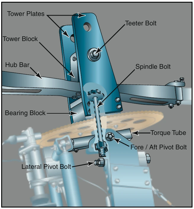
[Figure 18-1] In this system, the rotor head is mounted on a spindle, which may be tilted for control. The rotor blades are attached to a hub bar that may or may not have adjustments for varying the blade pitch. A coning angle, determined by projections of blade weight, rotor speed, and load to be carried, is built into the hub bar. This minimizes hub bar bending moments and eliminates the need for a coning hinge, which is used in more complex rotor systems. A tower block provides the undersling and attachment to the rotor head by the teeter bolt. The rotor head is comprised of a bearing block in which the bearing is mounted and onto which the tower plates are attached. The spindle (commonly, a vertically oriented bolt) attaches the rotating portion of the head to the non-rotating torque tube. The torque tube is mounted to the airframe through attachments allowing both lateral and longitudinal movement. This allows the movement through which control is achieved.
Fully Articulated Rotor System
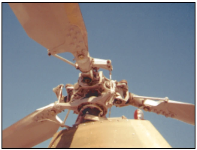
The fully articulated rotor system is found on some gyroplanes. As with helicopter-type rotor systems, the articulated rotor system allows the manipulation of rotor blade pitch while in flight. This system is significantly more complicated than the teeter-head, as it requires hinges that allow each rotor blade to flap, feather, and lead or lag independently. [Figure 18-2] When used, the fully articulated rotor system of a gyroplane is very similar to those used on helicopters, which is explained in depth in Chapter 5—Helicopter Systems, Main Rotor Systems. One major advantage of using a fully articulated rotor in gyroplane design is that it usually allows jump takeoff capability. Rotor characteristics required for a successful jump takeoff must include a method of collective pitch change, a blade with sufficient inertia, and a prerotation mechanism capable of approximately 150 percent of rotor flight r.p.m.
Coning Angle— An angular deflection of the rotor blades upward from the rotor hub.
Undersling— A design characteristic that prevents the distance between the rotor mast axis and the center of mass of each rotor blade from changing as the blades teeter. This precludes Coriolis Effect from acting on the speed of the rotor system. Undersling is further explained in Chapter 3—Aerodynamics of Flight, Coriolis Effect (Law of Conservation of Angular Momentum).
Incorporating rotor blades with high inertia potential is desirable in helicopter design and is essential for jump takeoff gyroplanes. A rotor hub design allowing the rotor speed to exceed normal flight r.p.m. by over 50 percent is not found in helicopters, and predicates a rotor head design particular to the jump takeoff gyroplane, yet very similar to that of the helicopter.
Prerotator
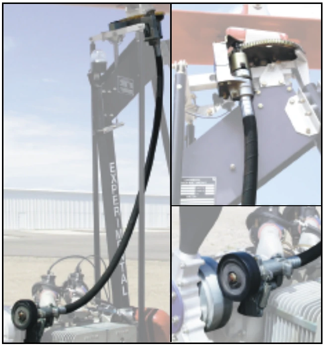
Prior to takeoff, the gyroplane rotor must first achieve a rotor speed sufficient to create the necessary lift.
This is accomplished on very basic gyroplanes by initially spinning the blades by hand. The aircraft is then taxied with the rotor disc tilted aft, allowing airflow through the system to accelerate it to flight r.p.m.