
Chapter 2
General Aerodynamics
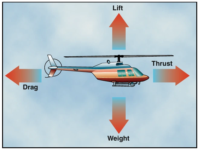
There are four forces acting on a helicopter in flight.
They are lift, weight, thrust, and drag. [Figure 2-1] Lift is the upward force created by the effect of airflow as it passes around an airfoil. Weight opposes lift and is caused by the downward pull of gravity. Thrust is the force that propels the helicopter through the air.
Opposing lift and thrust is drag, which is the retarding force created by development of lift and the movement of an object through the air.
Airfoil
Before beginning the discussion of lift, you need to be aware of certain aerodynamic terms that describe an airfoil and the interaction of the airflow around it.
An airfoil is any surface, such as an airplane wing or a helicopter rotor blade, which provides aerodynamic force when it interacts with a moving stream of air.
Although there are many different rotor blade airfoil designs, in most helicopter flight conditions, all airfoils perform in the same manner.
Engineers of the first helicopters designed relatively thick airfoils for their structural characteristics.
Because the rotor blades were very long and slender, it was necessary to incorporate more structural rigidity into them. This prevented excessive blade droop when the rotor system was idle, and minimized blade twisting while in flight. The airfoils were also designed to be symmetrical, which means they had the same camber (curvature) on both the upper and lower surfaces.
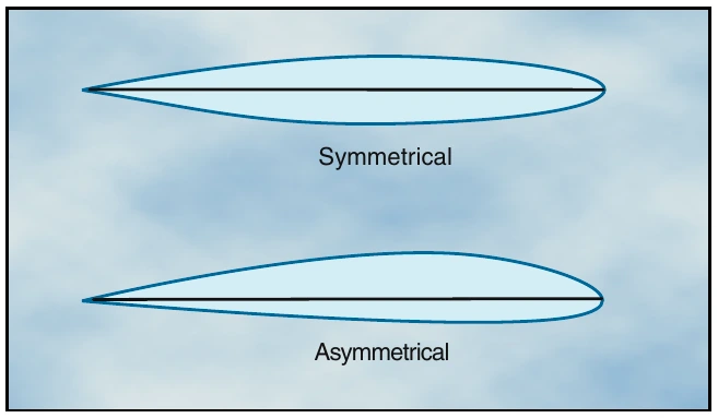
Symmetrical blades are very stable, which helps keep blade twisting and flight control loads to a minimum.
[Figure 2-2] This stability is achieved by keeping the center of pressure virtually unchanged as the angle of attack changes. Center of pressure is the imaginary point on the chord line where the resultant of all aerodynamic forces are considered to be concentrated.
Today, designers use thinner airfoils and obtain the required rigidity by using composite materials. In addition, airfoils are asymmetrical in design, meaning the upper and lower surface do not have the same camber.
Normally these airfoils would not be as stable, but this can be corrected by bending the trailing edge to produce the same characteristics as symmetrical airfoils. This is called “reflexing.” Using this type of rotor blade allows the rotor system to operate at higher forward speeds.
One of the reasons an asymmetrical rotor blade is not as stable is that the center of pressure changes with changes in angle of attack. When the center of pressure lifting force is behind the pivot point on a rotor blade, it tends to cause the rotor disc to pitch up. As the angle of attack increases, the center of pressure moves forward.
If it moves ahead of the pivot point, the pitch of the rotor disc decreases. Since the angle of attack of the rotor blades is constantly changing during each cycle of rotation, the blades tend to flap, feather, lead, and lag to a greater degree.
When referring to an airfoil, the span is the distance from the rotor hub to the blade tip. Blade twist refers to a changing chord line from the blade root to the tip.
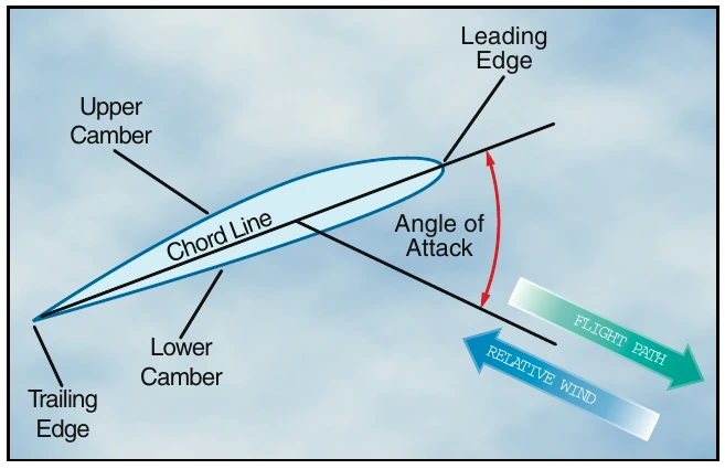
Twisting a rotor blade causes it to produce a more even amount of lift along its span. This is necessary because rotational velocity increases toward the blade tip. The leading edge is the first part of the airfoil to meet the oncoming air. [Figure 2-3] The trailing edge is the aft portion where the airflow over the upper surface joins the airflow under the lower surface. The chord line is an imaginary straight line drawn from the leading to the trailing edge. The camber is the curvature of the airfoil’s upper and lower surfaces. The relative wind is the wind moving past the airfoil. The direction of this wind is relative to the attitude, or position, of the airfoil and is always parallel, equal, and opposite in direction to the flight path of the airfoil. The angle of attack is the angle between the blade chord line and the direction of the relative wind.