Chapter 3
Aerodynamics of Flight
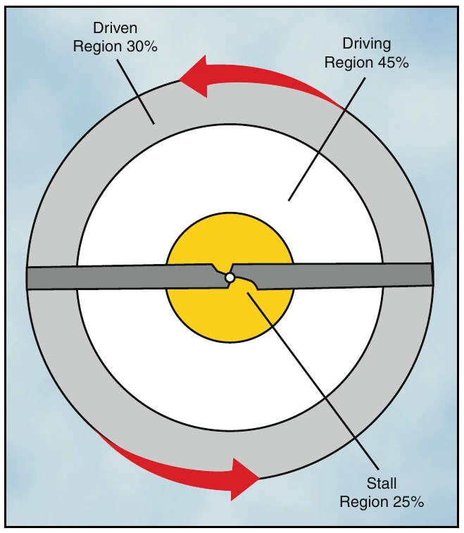
Figure 3-22 shows four blade sections that illustrate force vectors. Part A is the driven region, B and D are points of equilibrium, part C is the driving region, and part E is the stall region. Force vectors are different in each region because rotational relative wind is slower near the blade root and increases continually toward the blade tip. Also, blade twist gives a more positive angle of attack in the driving region than in the driven region. The combination of the inflow up through the rotor with rotational relative wind produces different combinations of aerodynamic force at every point along the blade.
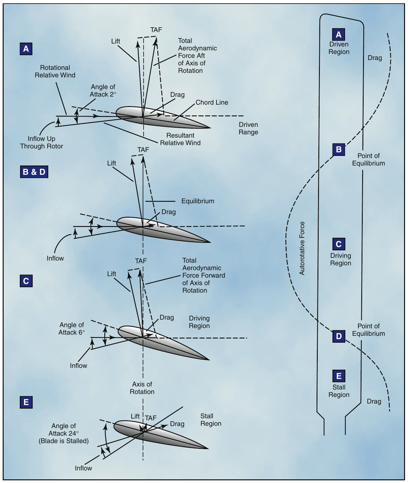
The driven region, also called the propeller region, is nearest the blade tips. Normally, it consists of about 30 percent of the radius. In the driven region, part A of figure 3-22, the total aerodynamic force acts behind the axis of rotation, resulting in a overall drag force. The driven region produces some lift, but that lift is offset by drag. The overall result is a deceleration in the rotation of the blade. The size of this region varies with the blade pitch, rate of descent, and rotor r.p.m. When changing autorotative r.p.m., blade pitch, or rate of descent, the size of the driven region in relation to the other regions also changes.
There are two points of equilibrium on the blade—one between the driven region and the driving region, and one between the driving region and the stall region. At points of equilibrium, total aerodynamic force is aligned with the axis of rotation. Lift and drag are produced, but the total effect produces neither acceleration nor deceleration.
The driving region, or autorotative region, normally lies between 25 to 70 percent of the blade radius. Part C of figure 3-22 shows the driving region of the blade, which produces the forces needed to turn the blades during autorotation. Total aerodynamic force in the driving region is inclined slightly forward of the axis of rotation, producing a continual acceleration force. This inclination supplies thrust, which tends to accelerate the rotation of the blade. Driving region size varies with blade pitch setting, rate of descent, and rotor r.p.m.
By controlling the size of this region you can adjust autorotative r.p.m. For example, if the collective pitch is raised, the pitch angle increases in all regions. This causes the point of equilibrium to move inboard along the blade’s span, thus increasing the size of the driven region. The stall region also becomes larger while the driving region becomes smaller. Reducing the size of the driving region causes the acceleration force of the driving region and r.p.m. to decrease.
The inner 25 percent of the rotor blade is referred to as the stall region and operates above its maximum angle of attack (stall angle) causing drag which tends to slow rotation of the blade. Part E of figure 3-22 depicts the stall region.
A constant rotor r.p.m. is achieved by adjusting the collective pitch so blade acceleration forces from the driving region are balanced with the deceleration forces from the driven and stall regions.
Autorotation (Forward Flight)
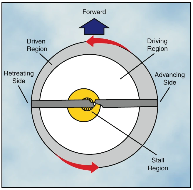
Autorotative force in forward flight is produced in exactly the same manner as when the helicopter is descending vertically in still air. However, because forward speed changes the inflow of air up through the rotor disc, all three regions move outboard along the blade span on the retreating side of the disc where angle of attack is larger, as shown in figure 3-23. With lower angles of attack on the advancing side blade, more of that blade falls in the driven region. On the retreating side, more of the blade is in the stall region. A small section near the root experiences a reversed flow, therefore the size of the driven region on the retreating side is reduced.