Chapter 3
Aerodynamics of Flight
Translational lift is also present in a stationary hover if the wind speed is approximately 16 to 24 knots. In normal operations, always utilize the benefit of translational lift, especially if maximum performance is needed.
Induced Flow
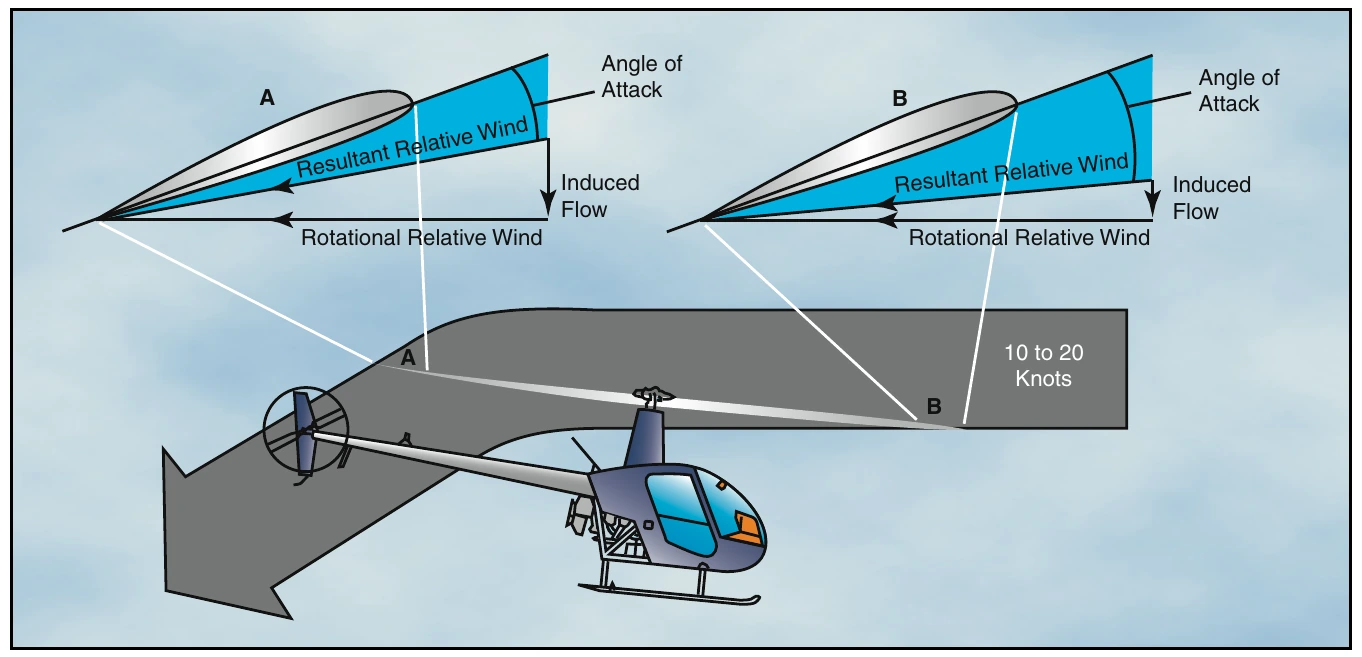
As the rotor blades rotate they generate what is called rotational relative wind. This airflow is characterized as flowing parallel and opposite the rotor’s plane of rotation and striking perpendicular to the rotor blade’s leading edge. This rotational relative wind is used to generate lift. As rotor blades produce lift, air is accelerated over the foil and projected downward. Anytime a helicopter is producing lift, it moves large masses of air vertically and down through the rotor system. This downwash or induced flow can significantly change the efficiency of the rotor system. Rotational relative wind combines with induced flow to form the resultant relative wind. As induced flow increases, resultant relative wind becomes less horizontal. Since angle of attack is determined by measuring the difference between the chord line and the resultant relative wind, as the resultant relative wind becomes less horizontal, angle of attack decreases. [Figure 3-13]
Transverse Flow Effect
As the helicopter accelerates in forward flight, induced flow drops to near zero at the forward disc area and increases at the aft disc area. This increases the angle of attack at the front disc area causing the rotor blade to flap up, and reduces angle of attack at the aft disc area causing the rotor blade to flap down. Because the rotor acts like a gyro, maximum displacement occurs 90° in the direction of rotation. The result is a tendency for the helicopter to roll slightly to the right as it accelerates through approximately 20 knots or if the headwind is approximately 20 knots.
You can recognize transverse flow effect because of increased vibrations of the helicopter at airspeeds just below effective translational lift on takeoff and after passing through effective translational lift during landing. To counteract transverse flow effect, a cyclic input needs to be made.
Dissymmetry of Lift
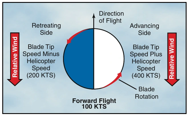
When the helicopter moves through the air, the relative airflow through the main rotor disc is different on the advancing side than on the retreating side. The relative wind encountered by the advancing blade is increased by the forward speed of the helicopter, while the relative wind speed acting on the retreating blade is reduced by the helicopter’s forward airspeed.
Therefore, as a result of the relative wind speed, the advancing blade side of the rotor disc produces more lift than the retreating blade side. This situation is defined as dissymmetry of lift. [Figure 3-14]
If this condition was allowed to exist, a helicopter with a counterclockwise main rotor blade rotation would roll to the left because of the difference in lift. In reality, the main rotor blades flap and feather automatically to equalize lift across the rotor disc. Articulated rotor systems, usually with three or more blades, incorporate a horizontal hinge (flapping hinge) to allow the individual rotor blades to move, or flap up and down as they rotate. A semirigid rotor system (two blades) utilizes a teetering hinge, which allows the blades to flap as a unit. When one blade flaps up, the other flaps down.
As shown in figure 3-15, as the rotor blade reaches the advancing side of the rotor disc (A), it reaches its maximum upflap velocity. When the blade flaps upward, the angle between the chord line and the resultant relative wind decreases. This decreases the angle of attack, which reduces the amount of lift produced by the blade.
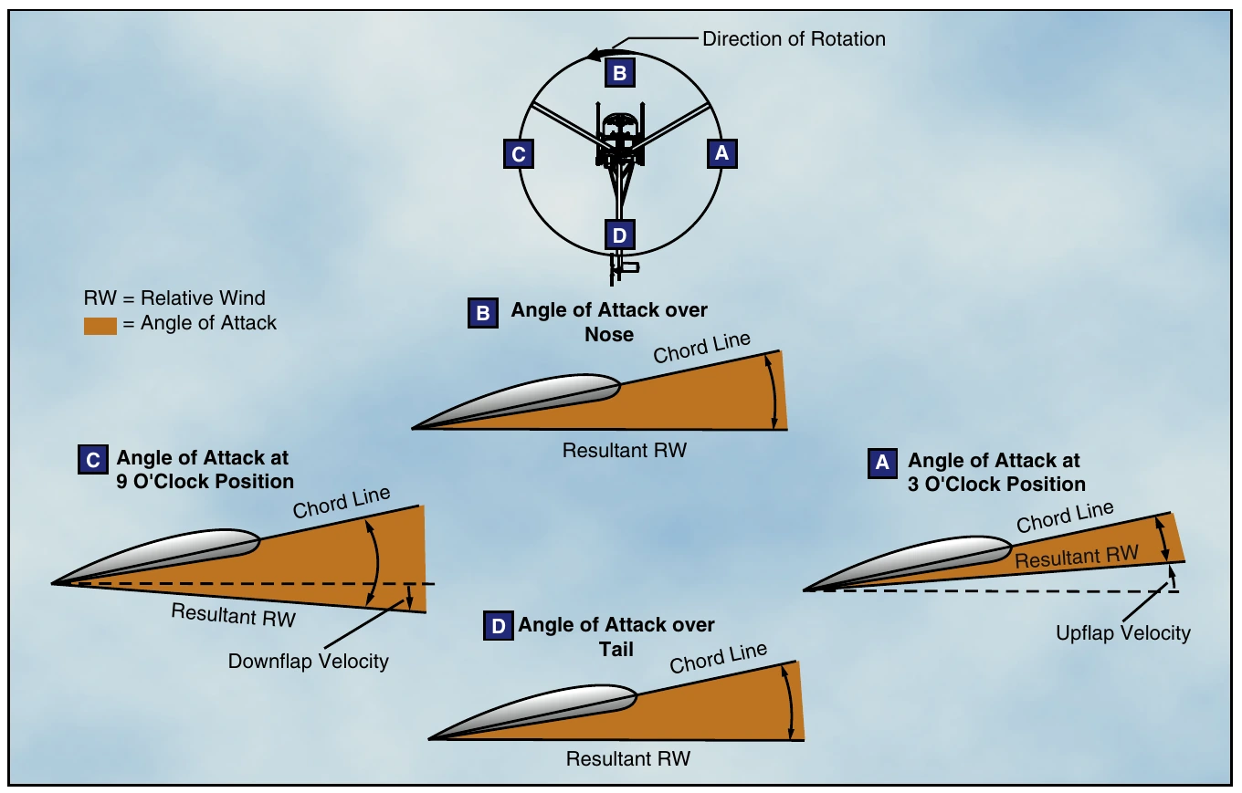
At position (C) the rotor blade is now at its maximum downflapping velocity. Due to downflapping, the angle between the chord line and the resultant relative wind increases. This increases the angle of attack and thus the amount of lift produced by the blade.
The combination of blade flapping and slow relative wind acting on the retreating blade normally limits the maximum forward speed of a helicopter. At a high forward speed, the retreating blade stalls because of a high angle of attack and slow relative wind speed. This situation is called retreating blade stall and is evidenced by a nose pitch up, vibration, and a rolling tendency—usually to the left in helicopters with counterclockwise blade rotation.
You can avoid retreating blade stall by not exceeding the never-exceed speed. This speed is designated V_NE and is usually indicated on a placard and marked on the airspeed indicator by a red line.
During aerodynamic flapping of the rotor blades as they compensate for dissymmetry of lift, the advancing blade achieves maximum upflapping displacement over the nose and maximum downflapping displacement over the tail. This causes the tip-path plane to tilt to the rear and is referred to as blowback. Figure 3-16 shows how the rotor disc was originally oriented with the front down following the initial cyclic input, but as airspeed is gained and flapping eliminates dissymmetry of lift, the front of the disc comes up, and the back of the disc goes down. This reorientation of the rotor disc changes the direction in which total rotor thrust acts so that the helicopter’s forward speed slows, but can be corrected with cyclic input.
V_NE— The speed beyond which an aircraft should never be operated. V_NE can change with altitude, density altitude, and weight.