
Chapter 5
Helicopter Systems
By knowing the various systems on a helicopter, you will be able to more easily recognize potential problems, and if a problem arises, you will have a better understanding of what to do to correct the situation.
Engines
The two most common types of engines used in helicopters are the reciprocating engine and the turbine engine. Reciprocating engines, also called piston engines, are generally used in smaller helicopters. Most training helicopters use reciprocating engines because they are relatively simple and inexpensive to operate.
Turbine engines are more powerful and are used in a wide variety of helicopters. They produce a tremendous amount of power for their size but are generally more expensive to operate.
Reciprocating Engine
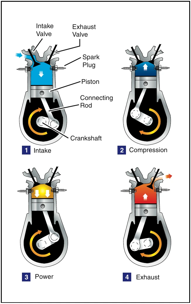
The reciprocating engine consists of a series of pistons connected to a rotating crankshaft. As the pistons move up and down, the crankshaft rotates. The reciprocating engine gets its name from the back-and-forth movement of its internal parts. The four-stroke engine is the most common type, and refers to the four different cycles the engine undergoes to produce power. [Figure 5-1]
When the piston moves away from the cylinder head on the intake stroke, the intake valve opens and a mixture of fuel and air is drawn into the combustion chamber.
As the cylinder moves back towards the cylinder head, the intake valve closes, and the fuel/air mixture is compressed. When compression is nearly complete, the spark plugs fire and the compressed mixture is ignited to begin the power stroke. The rapidly expanding gases from the controlled burning of the fuel/air mixture drive the piston away from the cylinder head, thus providing power to rotate the crankshaft. The piston then moves back toward the cylinder head on the exhaust stroke where the burned gasses are expelled through the opened exhaust valve.
Even when the engine is operated at a fairly low speed, the four-stroke cycle takes place several hundred times each minute. In a four-cylinder engine, each cylinder operates on a different stroke. Continuous rotation of a crankshaft is maintained by the precise timing of the power strokes in each cylinder.
Turbine Engine
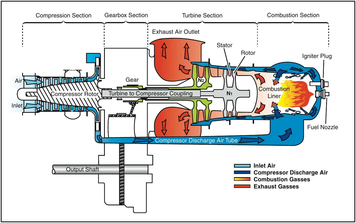
The gas turbine engine mounted on most helicopters is made up of a compressor, combustion chamber, turbine, and gearbox assembly. The compressor compresses the air, which is then fed into the combustion chamber where atomized fuel is injected into it. The fuel/air mixture is ignited and allowed to expand. This combustion gas is then forced through a series of turbine wheels causing them to turn. These turbine wheels provide power to both the engine compressor and the main rotor system through an output shaft. The combustion gas is finally expelled through an exhaust outlet. [Figure 5-2]
Compressor
The compressor may consist of an axial compressor, a centrifugal compressor, or both. An axial compressor consists of two main elements, the rotor and the stator.
The rotor consists of a number of blades fixed on a rotating spindle and resembles a fan. As the rotor turns, air is drawn rearwards. Stator vanes are arranged in fixed rows between the rotor blades and act as a diffuser at each stage to decrease air velocity and increase air pressure. There may be a number of rows of rotor blades and stator vanes. Each row constitutes a pressure stage, and the number of stages depends on the amount of air and pressure rise required for the particular engine.
A centrifugal compressor consists of an impeller, diffuser, and a manifold. The impeller, which is a forged disc with integral blades, rotates at a high speed to draw air in and expel it at an accelerated rate. The air then passes through the diffuser which slows the air down. When the velocity of the air is slowed, static pressure increases, resulting in compressed, high-pressure air. The high pressure air then passes through the compressor manifold where it is distributed to the combustion chamber.
Combustion Chamber
Unlike a piston engine, the combustion in a turbine engine is continuous. An igniter plug serves only to ignite the fuel/air mixture when starting the engine.
Once the fuel/air mixture is ignited, it will continue to burn as long as the fuel/air mixture continues to be present. If there is an interruption of fuel, air, or both, combustion ceases. This is known as a “flame-out,” and the engine has to be restarted or re-lit. Some helicopters are equipped with auto-relight, which automatically activates the igniters to start combustion if the engine flames out.