
Chapter 5
Helicopter Systems
Turbine
The turbine section consists of a series of turbine wheels that are used to drive the compressor section and the rotor system. The first stage, which is usually referred to as the gas producer or N may consist of one or more turbine wheels. This stage drives the components necessary to complete the turbine cycle making the engine self-sustaining. Common components driven by the N stage are the compressor, oil pump, and fuel pump. The second stage, which may also consist of one or more wheels, is dedicated to driving the main rotor system and accessories from the engine gearbox. This is referred to as the power turbine (N or N ).
2 r If the first and second stage turbines are mechanically coupled to each other, the system is said to be a direct-drive engine or fixed turbine. These engines share a common shaft, which means the first and second stage turbines, and thus the compressor and output shaft, are connected.
On most turbine assemblies used in helicopters, the first stage and second stage turbines are not mechanically connected to each other. Rather, they are mounted on independent shafts and can turn freely with respect to each other. This is referred to as a “free turbine.” When the engine is running, the combustion gases pass through the first stage turbine to drive the compressor rotor, and then past the independent second stage turbine, which turns the gearbox to drive the output shaft.
Transmission System
The transmission system transfers power from the engine to the main rotor, tail rotor, and other accessories. The main components of the transmission system are the main rotor transmission, tail rotor drive system, clutch, and freewheeling unit. Helicopter transmissions are normally lubricated and cooled with their own oil supply. A sight gauge is provided to check the oil level. Some transmissions have chip detectors located in the sump. These detectors are wired to warning lights located on the pilot’s instrument panel that illuminate in the event of an internal problem.
Main Rotor Transmission
The primary purpose of the main rotor transmission is to reduce engine output r.p.m. to optimum rotor r.p.m. This reduction is different for the various helicopters, but as an example, suppose the engine r.p.m. of a specific helicopter is 2,700. To achieve a rotor speed of 450 r.p.m. would require a 6 to 1 reduction. A 9 to 1 reduction would mean the rotor would turn at 300 r.p.m.
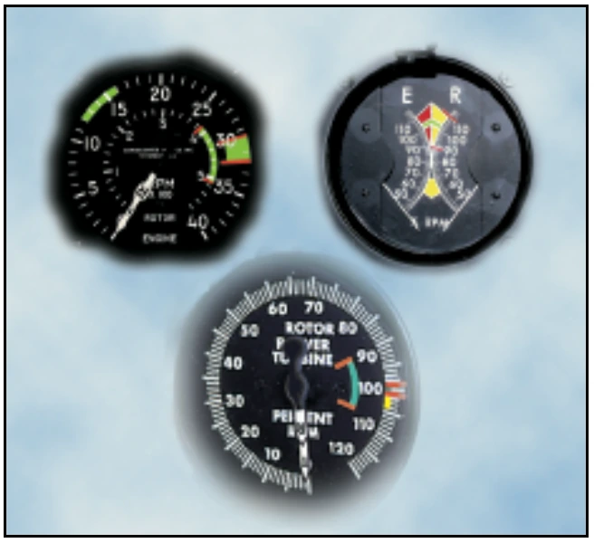
Most helicopters use a dual-needle tachometer to show both engine and rotor r.p.m. or a percentage of engine and rotor r.p.m. The rotor r.p.m. needle normally is used only during clutch engagement to monitor rotor acceleration, and in autorotation to maintain r.p.m. within prescribed limits. [Figure 5-3]
In helicopters with horizontally mounted engines, another purpose of the main rotor transmission is to change the axis of rotation from the horizontal axis of the engine to the vertical axis of the rotor shaft.
Tail Rotor Drive System
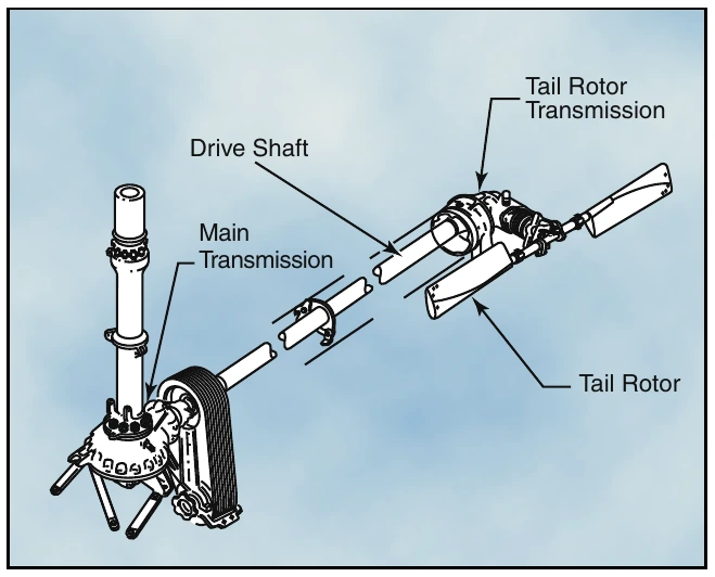
The tail rotor drive system consists of a tail rotor drive shaft powered from the main transmission and a tail rotor transmission mounted at the end of the tail boom.
The drive shaft may consist of one long shaft or a series of shorter shafts connected at both ends with flexible couplings. This allows the drive shaft to flex with the tail boom. The tail rotor transmission provides a right angle drive for the tail rotor and may also include gearing to adjust the output to optimum tail rotor r.p.m. [Figure 5-4]
Chip Detector— A chip detector is a warning device that alerts you to any abnormal wear in a transmission or engine. It consists of a magnetic plug located within the transmission. The magnet attracts any ferrous metal particles that have come loose from the bearings or other transmission parts. Most chip detectors send a signal to lights located on the instrument panel that illuminate when ferrous metal particles are picked up.
Clutch
In a conventional airplane, the engine and propeller are permanently connected. However, in a helicopter there is a different relationship between the engine and the rotor. Because of the greater weight of a rotor in relation to the power of the engine, as compared to the weight of a propeller and the power in an airplane, the rotor must be disconnected from the engine when you engage the starter. A clutch allows the engine to be started and then gradually pick up the load of the rotor.
On free turbine engines, no clutch is required, as the gas producer turbine is essentially disconnected from the power turbine. When the engine is started, there is little resistance from the power turbine. This enables the gas producer turbine to accelerate to normal idle speed without the load of the transmission and rotor system dragging it down. As the gas pressure increases through the power turbine, the rotor blades begin to turn, slowly at first and then gradually accelerate to normal operating r.p.m.
On reciprocating helicopters, the two main types of clutches are the centrifugal clutch and the belt drive clutch.