
Chapter 5
Helicopter Systems
Centrifugal Clutch
The centrifugal clutch is made up of an inner assembly and a outer drum. The inner assembly, which is connected to the engine driveshaft, consists of shoes lined with material similar to automotive brake linings. At low engine speeds, springs hold the shoes in, so there is no contact with the outer drum, which is attached to the transmission input shaft. As engine speed increases, centrifugal force causes the clutch shoes to move outward and begin sliding against the outer drum. The transmission input shaft begins to rotate, causing the rotor to turn, slowly at first, but increasing as the friction increases between the clutch shoes and transmission drum. As rotor speed increases, the rotor tachometer needle shows an increase by moving toward the engine tachometer needle. When the two needles are superimposed, the engine and the rotor are synchronized, indicating the clutch is fully engaged and there is no further slippage of the clutch shoes.
Belt Drive Clutch
Some helicopters utilize a belt drive to transmit power from the engine to the transmission. A belt drive consists of a lower pulley attached to the engine, an upper pulley attached to the transmission input shaft, a belt or a series of V-belts, and some means of applying tension to the belts. The belts fit loosely over the upper and lower pulley when there is no tension on the belts. This allows the engine to be started without any load from the transmission. Once the engine is running, tension on the belts is gradually increased.
When the rotor and engine tachometer needles are superimposed, the rotor and the engine are synchronized, and the clutch is then fully engaged.
Advantages of this system include vibration isolation, simple maintenance, and the ability to start and warm up the engine without engaging the rotor.
Freewheeling Unit
Since lift in a helicopter is provided by rotating airfoils, these airfoils must be free to rotate if the engine fails. The freewheeling unit automatically disengages the engine from the main rotor when engine r.p.m. is less than main rotor r.p.m. This allows the main rotor to continue turning at normal in-flight speeds. The most common freewheeling unit assembly consists of a one-way sprag clutch located between the engine and main rotor transmission.
This is usually in the upper pulley in a piston helicopter or mounted on the engine gearbox in a turbine helicopter.
When the engine is driving the rotor, inclined surfaces in the spray clutch force rollers against an outer drum. This prevents the engine from exceeding transmission r.p.m. If the engine fails, the rollers move inward, allowing the outer drum to exceed the speed of the inner portion. The transmission can then exceed the speed of the engine. In this condition, engine speed is less than that of the drive system, and the helicopter is in an autorotative state.
Main Rotor System
Main rotor systems are classified according to how the main rotor blades move relative to the main rotor hub.
As was described in Chapter 1—Introduction to the Helicopter, there are three basic classifications: fully articulated, semirigid, or rigid. Some modern rotor systems use a combination of these types.
Fully Articulated Rotor System
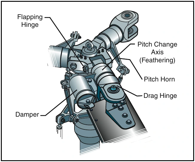
In a fully articulated rotor system, each rotor blade is attached to the rotor hub through a series of hinges, which allow the blade to move independently of the others. These rotor systems usually have three or more blades. [Figure 5-5] The horizontal hinge, called the flapping hinge, allows the blade to move up and down. This movement is called flapping and is designed to compensate for dissymetry of lift. The flapping hinge may be located at varying distances from the rotor hub, and there may be more than one hinge.
The vertical hinge, called the lead-lag or drag hinge, allows the blade to move back and forth. This movement is called lead-lag, dragging, or hunting.
Dampers are usually used to prevent excess back and forth movement around the drag hinge. The purpose of the drag hinge and dampers is to compensate for the acceleration and deceleration caused by Coriolis Effect.
Each blade can also be feathered, that is, rotated around its spanwise axis. Feathering the blade means changing the pitch angle of the blade. By changing the pitch angle of the blades you can control the thrust and direction of the main rotor disc.