User-friendly explanations of instrument approach charts, planviews, profiles, minimums, airport diagrams, departures, arrivals, and visual procedures.
When appears in the Notes section below all other symbols it indicates a cold temperature altitude correction is required at that airport when the reported temperature is at or below the published temperature. Advise ATC with altitude correction. Advising ATC with altitude corrections is not required in the final segment. See Aeronautical Information Manual (AIM), Chapter 7, for guidance and additional information. For a complete list of cold temperature airports, see https://aeronav.faa.gov/d-tpp/Cold_Temp_Airports.pdf. When “ASR”, “PAR” or “ASR/PAR” appear in the Note section immediately below the “T” and “A” symbols it indicates there are published Radar Instrument Approach Minimums. Where radar is approved for approach control service, it is used not only for radar approaches (Airport Surveillance Radar [ASR] and Precision Approach Radar [PAR]) but is also used to provide vectors in conjunction with published non-radar approaches based on radio NAVAIDs (ILS, VOR, NDB, TACAN). Radar vectors can provide course guidance and expedite traffic to the final approach course of any established IAP or to the traffic pattern for a visual approach. Bottom Briefing Strip (Communications Information) The communications briefing strip contains communication information when available, in separate boxes, listed from left to right in the order that they would be used during arrival with the tower frequency box bolded: • ATIS, D-ATIS, AFIS (AK Only) or ASOS/AWOS frequencies (when available, ATIS or AFIS will be the only local weather frequency/s published) • The primary Approach Control (APP CON) name and frequencies; when the primary approach service is provided by other than Approach Control, e.g. FSS (Radio), Tower, Center, the appropriate air traffic facility call name is provided • The Control Tower (TOWER) name and frequencies, to include Precision Radar Monitoring (PRM) and frequency • Ground Control (GND CON) frequencies • Clearance Delivery (CLNC DEL) frequencies; where a Control Tower does not exist or is part-time, a remoted CLNC DEL may be listed. • Ground Communications Outlet (GCO) frequency • Common Traffic Advisory Frequency (CTAF), shown in parentheses when shares a frequency, e.g. UNICOM 122.8 (CTAF) • UNICOM or AUNICOM frequency (part-time and non-towered airports only) • Controller Pilot Data Link Communication (CPDLC) (part-time and non-towered airports only) Note: Part-time operations will be annotated with a star. Check Chart Supplement for times of operation. Note: Departure ATIS, CLNC DEL, and CPDLC will not be charted on the IAP at locations where the information is shown on the corresponding Airport Diagram.
Source page 105
PLANVIEW
The planview of the IAP charts provides an overhead view of the entire instrument approach procedure.The data on the planview is shown to scale, unless concentric rings, scale breaks or an inset have been used.
Planview Items
Approach Segments
The planview includes a graphical depiction of procedure entry through missed approach.
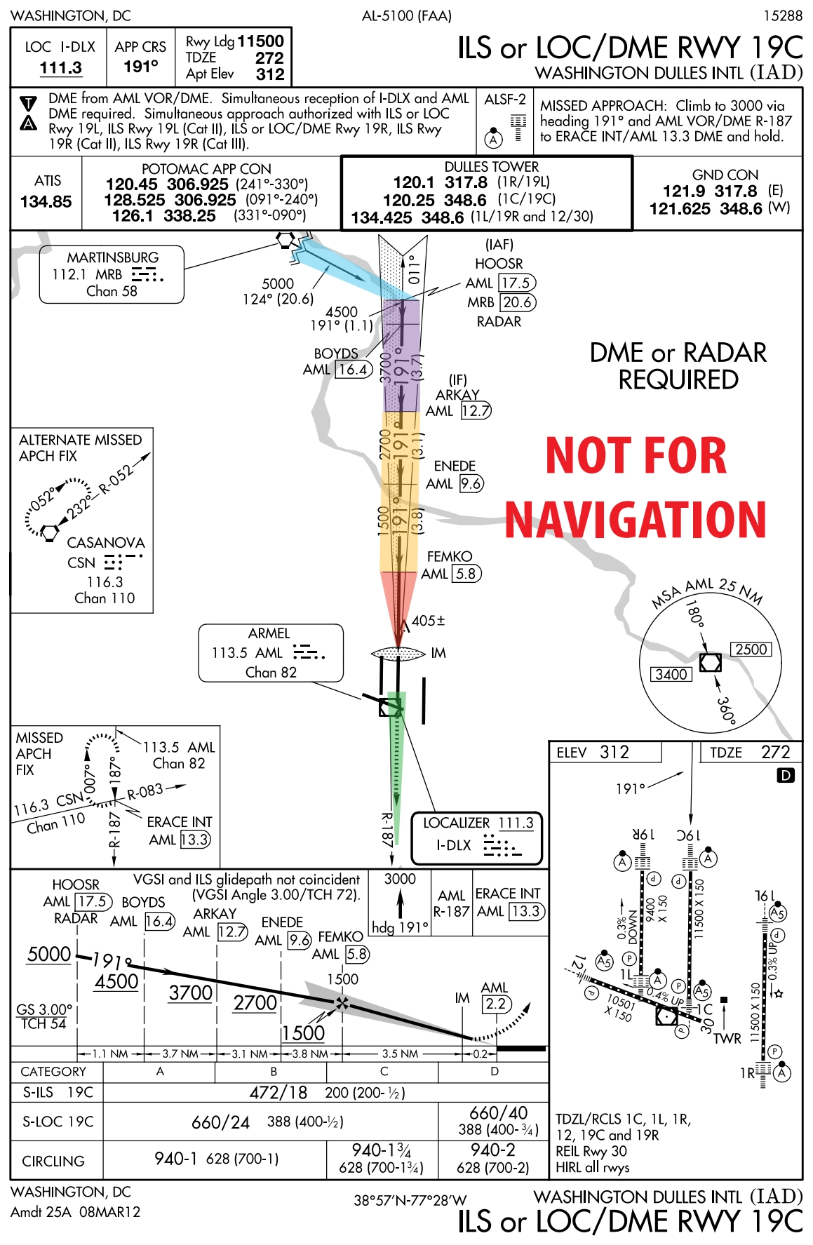
Simple IAP — Washington Dulles ILS/LOC DME RWY 19C with colored segments — source page 105.
Approach-segment colors — feeder/initial/intermediate/final/missed — source page 105.
PLANVIEW The planview of the IAP charts provides an overhead view of the entire instrument approach procedure.The data on the planview is shown to scale, unless concentric rings, scale breaks or an inset have been used. Planview Items Approach Segments Hydrography NAVAIDs International Boundary Area Navigation (RNAV) Waypoints Obstacles (Man-made, Terrain and Vegetation) Restrictive Airspeeds Special Use Airspace Restrictive Altitudes Minimum Safe Altitude Holding Patterns and Procedure Turns Terminal Arrival Areas Airports Helicopter (Copter) Procedures Relief (Contours) Approach Segments The planview includes a graphical depiction of procedure entry through missed approach. Simple IAP Example Legend: Feeder Route Initial Approach Intermediate Approach Final Approach Course Missed Approach NAVIGATION NOT FOR
Source page 106
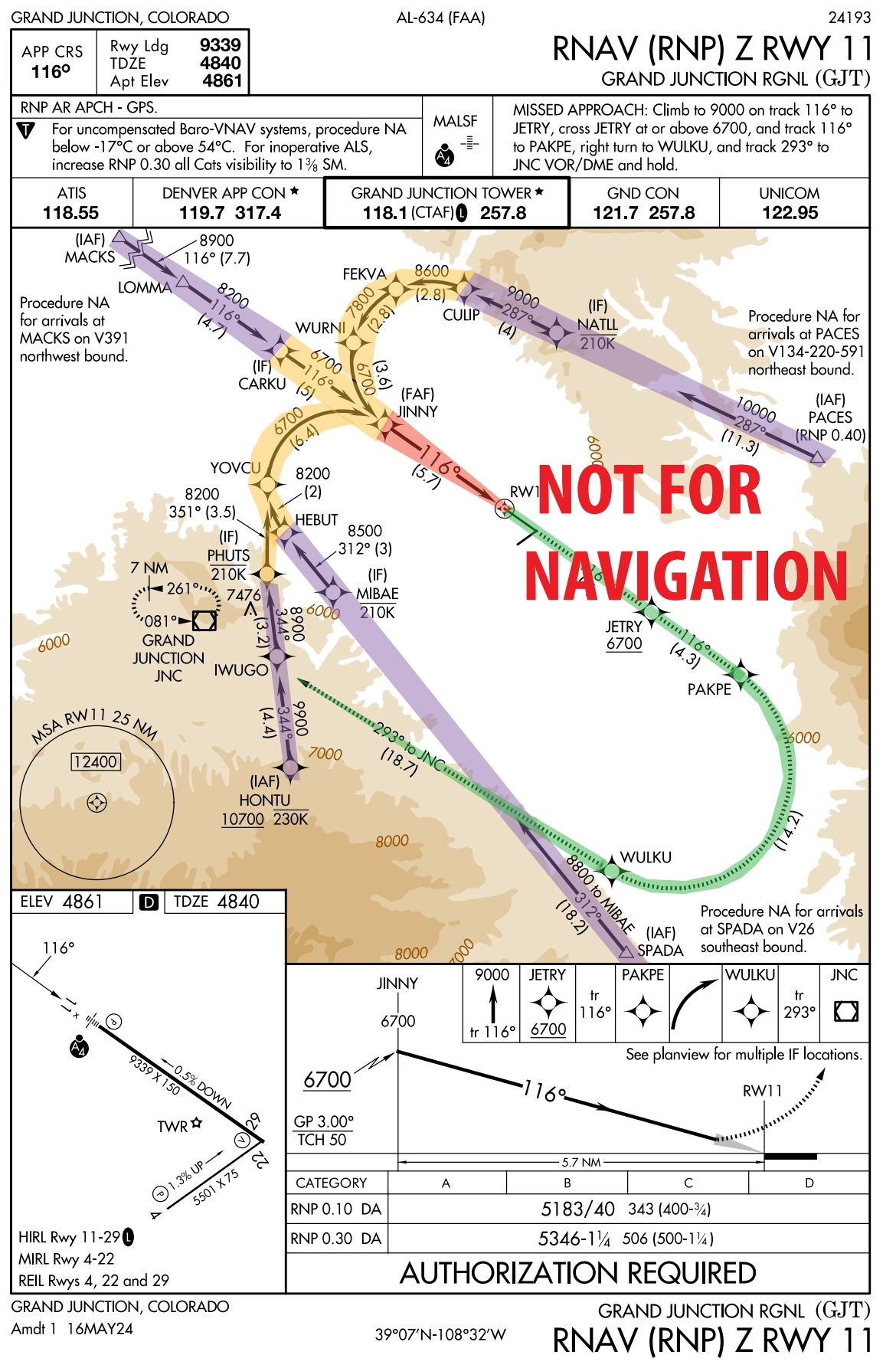
Complex IAP with RF legs — Grand Junction RNAV (RNP) Z RWY 11 — source page 106.
Feeder Routes (highlighted in blue - See Simple IAP Example on previous page) may be used to provide a transition from the enroute structure to the IAF.
Initial Approach (highlighted in purple in examples above) is the segment between the initial approach fix (IAF) and the intermediate fix (IF) or the point where the aircraft is established on the intermediate course or final approach course.
Intermediate Approach (highlighted in yellow in examples above) is the segment between the intermediate fix or point and the final approach fix.
Final Approach Course (highlighted in red in the examples above) is the segment between the final approach fix or point and the runway, airport, or missed approach point.
Missed Approach (highlighted in green in the example above) begins at the MAP and continues until the designated fix or waypoint. The missed approach track is shown as a hash marked line in the planview. If any portion of the missed approach procedure track falls outside of the area of the planview it will be shown in a separate box in the planview.
NOT FOR NAVIGATION Complex IAP Example with RF Legs • Feeder Routes (highlighted in blue - See Simple IAP Example on previous page) may be used to provide a transition from the enroute structure to the IAF. • Initial Approach (highlighted in purple in examples above) is the segment between the initial approach fix (IAF) and the intermediate fix (IF) or the point where the aircraft is established on the intermediate course or final approach course. • Intermediate Approach (highlighted in yellow in examples above) is the segment between the intermediate fix or point and the final approach fix. • Final Approach Course (highlighted in red in the examples above) is the segment between the final approach fix or point and the runway, airport, or missed approach point. • Missed Approach (highlighted in green in the example above) begins at the MAP and continues until the designated fix or waypoint. The missed approach track is shown as a hash marked line in the planview. If any portion of the missed approach procedure track falls outside of the area of the planview it will be shown in a separate box in the planview.
Source page 107
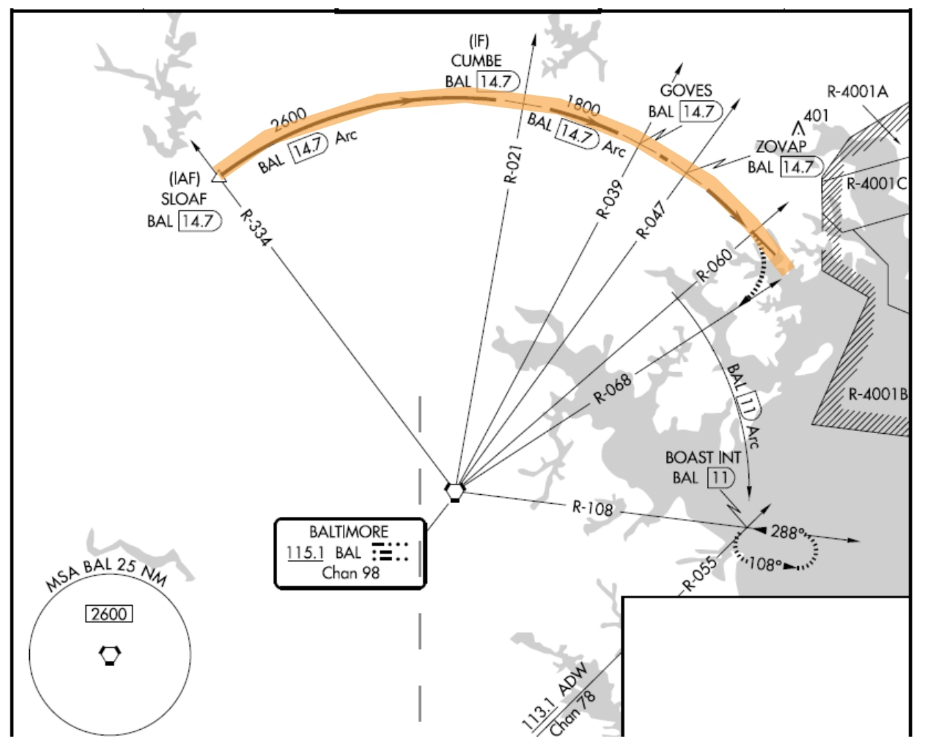
DME arcs or Radius-to-Fix legs (RF) are shown as smooth arcs from a designated start point to a designated terminus. RF legs depict the altitude and distance. In order to differentiate RF legs from Track to Fix (TF) legs on IAPs that contain one or more RF legs, the course value will always be shown on all TF legs.
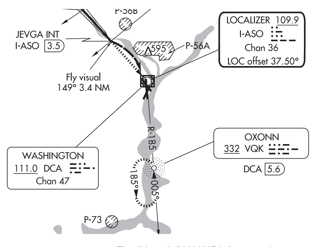
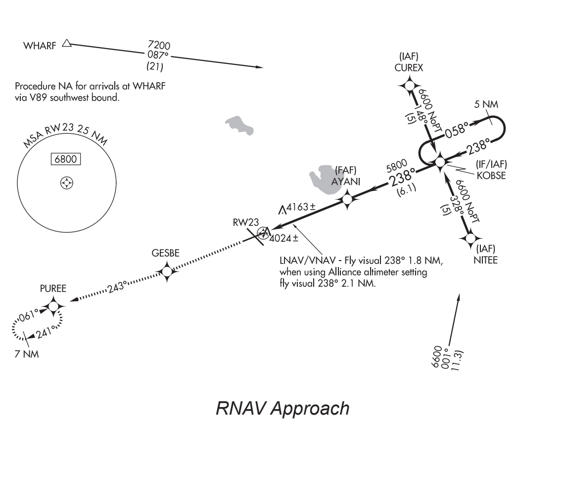
Visual segment - Instrument approach procedures, including Copter approach procedures, that terminate or have missed approaches prior to the airport/heliport, and are authorized to proceed visually, will depict the visual flight path by a dashed line symbol from the missed approach point to the airport. On RNAV charts where the visual track may only apply to a specific line of minima, the visual procedure track line will not be shown in the planview. There will be a note directed to that portion of the procedure track.
• DME arcs or Radius-to-Fix legs (RF) are shown as smooth arcs from a designated start point to a designated terminus. RF legs depict the altitude and distance. In order to differentiate RF legs from Track to Fix (TF) legs on IAPs that contain one or more RF legs, the course value will always be shown on all TF legs.
• Visual segment - Instrument approach… — source page 107.
Visual segment on a traditional NAVAID approach chart — source page 107.
RNAV-approach visual segment — source page 107.
• DME arcs or Radius-to-Fix legs (RF) are shown as smooth arcs from a designated start point to a designated terminus. RF legs depict the altitude and distance. In order to differentiate RF legs from Track to Fix (TF) legs on IAPs that contain one or more RF legs, the course value will always be shown on all TF legs. • Visual segment - Instrument approach procedures, including Copter approach procedures, that terminate or have missed approaches prior to the airport/heliport, and are authorized to proceed visually, will depict the visual flight path by a dashed line symbol from the missed approach point to the airport. On RNAV charts where the visual track may only apply to a specific line of minima, the visual procedure track line will not be shown in the planview. There will be a note directed to that portion of the procedure track. Traditional (NAVAID) Approach RNAV Approach
Cookie Preferences
We use cookies to operate this website, improve performance, understand site traffic, and personalize your experience. Essential cookies are always active because they are required for the website to function.
Required for basic site functionality and security.
Help us understand how visitors use the website so we can improve it.
May be used for advertising, remarketing, or social media features.
You can update your choices anytime using Cookie Settings. View Privacy Policy