User-friendly explanations of instrument approach charts, planviews, profiles, minimums, airport diagrams, departures, arrivals, and visual procedures.
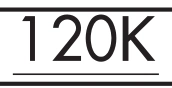
Minimum speed — 120K — source page 109.
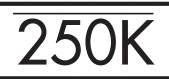
Maximum speed — 250K — source page 109.
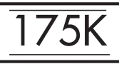
Mandatory speed — 175K — source page 109.
Restrictive altitudes are shown paired with their respective fix/ facility. Minimum, Maximum, Mandatory and Recommended Altitudes are shown.
Type | Description | Example
Recommended Altitude | Recommended altitude is depicted with no lines above or below it |
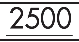
Minimum Altitude | Minimum altitude is depicted as a number with a line below it |
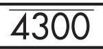
Maximum Altitude | Maximum altitude is depicted as a number with a line above it |
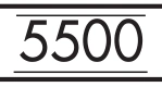
Mandatory Altitude | Mandatory altitude is depicted as a number with a line above and below it |
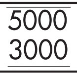
Mandatory Block Altitude | Mandatory block altitude is depicted with a minimum and a maximum altitude. |
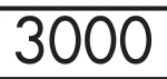
Recommended altitude — 3000 — source page 109.
Minimum altitude — 2500 — source page 109.
Maximum altitude — 4300 — source page 109.
Mandatory altitude — 5500 — source page 109.
Mandatory block altitude — 3000 to 5000 — source page 109.
Minimum route altitude example — source page 109.
Localizer Depiction The localizer is depicted in the Planview using the following symbol. The size of the charted localizer symbol does not serve as an indication of the service volume. Restrictive Airspeed Restrictive airspeeds are shown paired with their respective fix/facility. Type Description Example Recommended Speed Recommended speed is depicted with no lines above or below it Minimum Speed Minimum speed is depicted as a number with a line below it Maximum Speed Maximum speed is depicted as a number with a line above it Mandatory Speed Mandatory speed is depicted as a number with a line above and below it Altitudes Restrictive altitudes are shown paired with their respective fix/ facility. Minimum, Maximum, Mandatory and Recommended Altitudes are shown. Type Description Example Recommended Altitude Recommended altitude is depicted with no lines above or below it Minimum Altitude Minimum altitude is depicted as a number with a line below it Maximum Altitude Maximum altitude is depicted as a number with a line above it Mandatory Altitude Mandatory altitude is depicted as a number with a line above and below it Mandatory Block Altitude Mandatory block altitude is depicted with a minimum and a maximum altitude. Altitudes that are shown along a route are minimum altitudes.
Source page 110
Holding Patterns and Procedure Turns
Holding Patterns are used for many reasons, including deteriorating weather or high traffic volume. Holding might also be required following a missed approach. Each holding pattern has a fix, a direction to hold from the fix, and an airway, bearing, course, radial, or route on which the aircraft is to hold. These elements, along with the direction of the turns, define the holding pattern. Holding Patterns may not always be depicted to scale.
Holding-pattern examples — missed approach, HILPT, airway/non-standard restriction, arrival — source page 110.
If a holding pattern has a non-standard speed restriction, it will be depicted by an icon with the limiting air speed shown inside the holding pattern symbol. These elements, along with the direction of the turns, define the holding pattern. If two types of holds are located at the same point, the procedural holding pattern will be shown in-lieu of arrival or missed approach holding patterns. Timing or distance limits for Hold-in-lieu of Procedure Turn Holding Patterns will be shown.
Waypoints designated as a holding fix are shown as fly-by, without the circle around the symbol. However, in the event the holding fix/waypoint is also designated in all other parts of the procedure unrelated to holding with a fly-over function, then the holding fix/waypoint will be charted as a fly-over point.
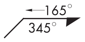
A procedure turn (PT) is the maneuver prescribed to perform a course reversal to establish the aircraft inbound on an intermediate or final approach course. The procedure turn or hold-in-lieu-of procedure turn is a required maneuver when it is depicted on the approach chart. However, the procedure turn or the hold-in-lieu-of PT is not permitted when the symbol “NoPT” is depicted on the initial segment being flown, when a RADAR VECTOR to the final approach course is provided, or when conducting a timed approach from a holding fix. The procedure turn will be shown in the planview and in the profile of the chart. In the planview, the tip of the procedure turn barb is shown at the procedure turn limit, e.g., 10 NM, 15 NM. Users should be aware that it is possible for there to be a terminal/feeder fix along the procedure track that is not associated with the procedure turn. Fixes associated with the procedure turn are depicted in the profile.
Procedure-turn symbol — outbound 165°, inbound 345° — source page 110.
Cookie Preferences
We use cookies to operate this website, improve performance, understand site traffic, and personalize your experience. Essential cookies are always active because they are required for the website to function.
Required for basic site functionality and security.
Help us understand how visitors use the website so we can improve it.
May be used for advertising, remarketing, or social media features.
You can update your choices anytime using Cookie Settings. View Privacy Policy