
Chapter 13
Transition to Multiengine Airplanes
The emphasis in a short-field approach is on configuration (full flaps), a stabilized approach with a constant angle of descent, and precise airspeed control. As part of a short-field approach and landing procedure, some AFM/POHs recommend a slightly slower than normal approach airspeed. If no such slower speed is published, use the AFM/POH-recommended normal approach speed.
Full flaps are used to provide the steepest approach angle. If obstacles are present, the approach should be planned so that no drastic power reductions are required after they are cleared. The power should be smoothly reduced to idle in the round out prior to touchdown. Pilots should keep in mind that the propeller blast blows over the wings providing some lift in addition to thrust. Reducing power significantly, just after obstacle clearance, usually results in a sudden, high sink rate that may lead to a hard landing. After the short-field touchdown, maximum stopping effort is achieved by retracting the wing flaps, adding back pressure to the elevator/stabilator, and applying heavy braking. However, if the runway length permits, the wing flaps should be left in the extended position until the airplane has been stopped clear of the runway. There is always a significant risk of retracting the landing gear instead of the wing flaps when flap retraction is attempted on the landing rollout.
Landing conditions that involve a short field, high winds, or strong crosswinds are just about the only situations where flap retraction on the landing rollout should be considered. When there is an operational need to retract the flaps just after touchdown, it needs to be done deliberately with the flap handle positively identified before it is moved.
Go-Around
When the decision to go around is made, the throttles should be advanced to takeoff power and pitch adjusted to arrest the sink rate. With adequate airspeed, the airplane should be placed in a climb pitch attitude. These actions, which are accomplished sequentially, arrest the sink rate and place the airplane in the proper attitude for transition to a climb. The initial target airspeed is VY or VX if obstructions are present. With sufficient airspeed, the flaps should be retracted from full to an intermediate position and the landing gear retracted when there is a positive rate of climb and no chance of runway contact. The remaining flaps should then be retracted. [Figure 13-11]
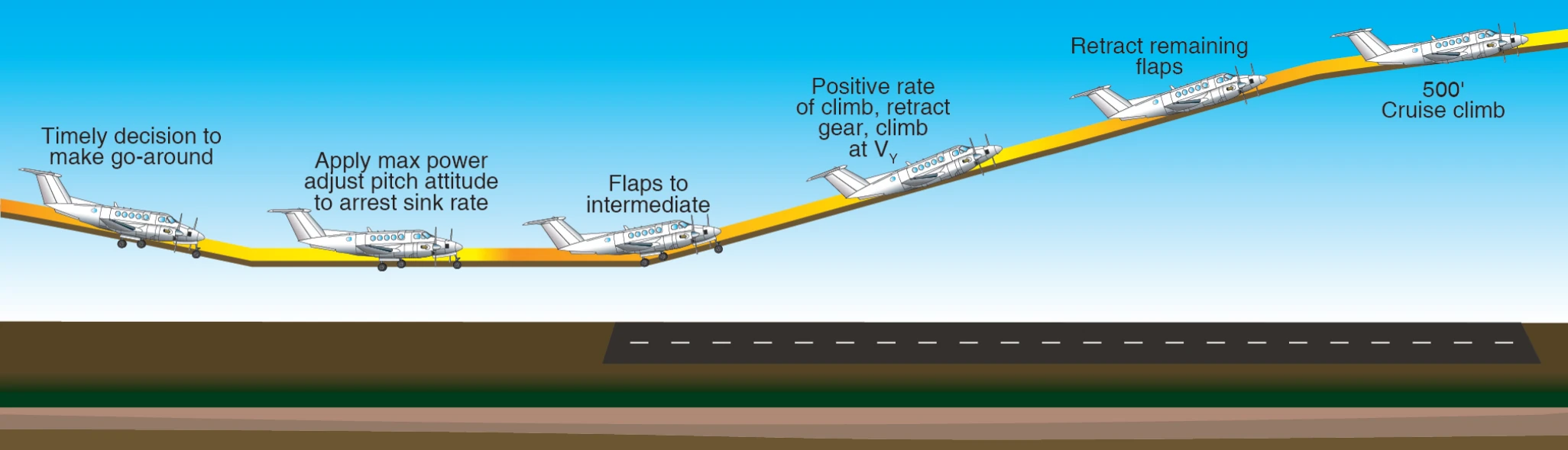
If the go-around was initiated due to conflicting traffic on the ground or aloft, the pilot should consider maneuvering to the side to keep the conflicting traffic in sight. This may involve a slight turn to offset from the runway/landing area.
If the airplane was in trim for the landing approach when the go-around was commenced, it soon requires a great deal of forward elevator/stabilator pressure as the airplane accelerates away in a climb. The pilot should apply appropriate forward pressure to maintain the desired pitch attitude. Trim should be commenced immediately. The balked landing checklist should be reviewed as work load permits.
Flaps should be retracted before the landing gear for two reasons. First, on most airplanes, full flaps produce more drag than the extended landing gear. Secondly, the airplane tends to settle somewhat with flap retraction, and the landing gear should be down in the event of an inadvertent, momentary touchdown.
Many multiengine airplanes have a landing gear retraction speed significantly less than the extension speed. Care should be exercised during the go-around not to exceed the retraction speed. If the pilot desires to return for a landing, it is essential to re-accomplish the entire before-landing checklist. An interruption to a pilot’s habit patterns, such as a go-around, is a classic scenario for a subsequent gear-up landing.
The preceding discussion about performing a go-around assumes that the maneuver was initiated from normal approach speeds or faster. If the go-around was initiated from a low airspeed, the initial pitch up to a climb attitude should be tempered with the necessity to maintain adequate flying speed throughout the maneuver. Examples of where this applies include a go-around initiated from the landing round out or recovery from a bad bounce, as well as a go-around initiated due to an inadvertent approach to a stall. The first priority is always to maintain control and obtain adequate flying speed. A few moments of level or near level flight may be required as the airplane accelerates up to climb speed.
Engine Inoperative Flight Principles
There are two main considerations for OEI operations—performance and control. Multiengine pilots learn to operate the airplane for maximum rate of climb performance at the blue radial indicated airspeed by training to fly without sideslip. Pilots also learn to recognize and recover from loss of directional control associated with the red radial indicated airspeed by performing a VMC demonstration. Since the object of a VMC demonstration is not performance, sideslip occurs during the maneuver. Detailed discussion on both the loss of directional control and maximum OEI climb performance follows.
Derivation of V
VMC is a speed established by the manufacturer, published in the AFM/POH, and marked on most airspeed indicators with a red radial line. A knowledgeable and competent multiengine pilot understands that VMC is not a fixed airspeed under all conditions. VMC is a fixed airspeed only for the very specific set of circumstances under which it was determined during aircraft certification. In reality, VMC varies with a variety of factors as outlined below. The VMC noted in practice and demonstration, or in actual OEI operation, could be less or even greater than the published value, depending on conditions and pilot technique.
Historically, in aircraft certification, VMC is the sea level calibrated airspeed at which, when the critical engine is suddenly made inoperative, it is possible to maintain control of the airplane with that engine still inoperative and then maintain straight flight at the same speed with an angle of bank not more than 5°.
The foregoing refers to the determination of VMC under dynamic conditions. This technique is only used by highly experienced test pilots during aircraft certification. It is unsafe to be attempted outside of these circumstances.
In aircraft certification, there is also a determination of VMC under static, or steady-state conditions. If there is a difference between the dynamic and static speeds, the higher of the two is published as VMC. The static determination is simply the ability to maintain straight flight at VMC with a bank angle of not more than 5°. This more closely resembles the VMC demonstration task in the practical test for a multiengine rating.
The AFM/POH-published VMC is determined with the critical engine inoperative. The critical engine is the engine whose failure had the most adverse effect on directional control. On twins with each engine rotating in conventional, clockwise rotation as viewed from the pilot's seat, the critical engine will be the left engine.
Multiengine airplanes are subject to P-factor just as single-engine airplanes are. The descending propeller blade of each engine will produce greater thrust than the ascending blade when the airplane is operated under power and at positive angles of attack. The descending propeller blade of the right engine is also a greater distance from the center of gravity, and therefore has a longer moment arm than the descending propeller blade of the left engine. As a result, failure of the left engine will result in the most asymmetrical thrust (adverse yaw) as the right engine will be providing the remaining thrust. [Figure 13-12]