
Chapter 13
Transition to Multiengine Airplanes
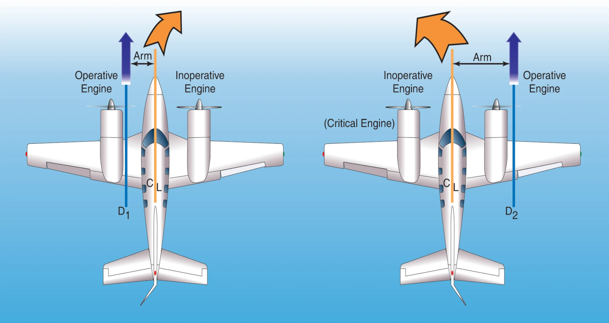
Many twins are designed with a counter-rotating right engine. With this design, the degree of asymmetrical thrust is the same with either engine inoperative. No engine is more critical than the other, and a VMC demonstration may be performed with either engine windmilling.
The following bullets describe the way several factors affect VMC speed for those multiengine airplanes often used during training, which were certified in accordance with historical 14 CFR part 23, section 23.149. They also describe the conditions used to determine the manufacturer's published speed. Historically, in aircraft certification, dynamic VMC has been determined under the following conditions outlined in historical 14 CFR part 23, section 23.149:
- Maximum available takeoff power initially on each engine (section 23.149(b)(1)). VMC increases as power is increased on the operating engine. With normally aspirated engines, VMC is highest at takeoff power and sea level, and decreases with altitude. With turbocharged engines, takeoff power, and therefore VMC, remains constant with increases in altitude up to the engine's critical altitude (the altitude where the engine can no longer maintain 100 percent power). Above the critical altitude, VMC decreases just as it would with a normally aspirated engine whose critical altitude is sea level. In order to avoid accidents, test pilots conduct VMC tests at a variety of altitudes, and the results of those tests are then extrapolated to a single, sea level value.
- All propeller controls in the recommended takeoff position throughout VMC determination (section 23.149(b)(5)). VMC increases with increased drag on the inoperative engine. VMC is highest, therefore, when the critical engine propeller is windmilling at the low pitch, high rpm blade angle. VMC is normally determined with the critical engine propeller windmilling in the takeoff position, unless the engine is equipped with an autofeather system.
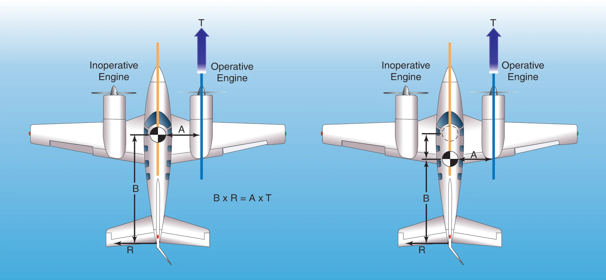
- Most unfavorable weight and center-of-gravity position (section 23.149(b)). VMC increases as the center-of-gravity (CG) is moved aft. The moment arm of the rudder is reduced, and therefore its effectivity is reduced, as the CG is moved aft. For a typical light twin, the aft-most CG limit is the most unfavorable CG position. Historically, 14 CFR part 23 calls for VMC to be determined at the most unfavorable weight. For twins certificated under CAR 3 or early 14 CFR part 23, the weight at which VMC was determined was not specified. VMC increases as weight is reduced. [Figure 13-13]
- Landing gear retracted (section 23.149(b)(4)). VMC increases when the landing gear is retracted. Extended landing gear aids directional stability, which tends to decrease VMC.
- Flaps in the takeoff position (section 23.149(b)(3)). This normally includes wing flaps and cowl flaps. For most twins, this will be 0° of flaps.
- Airplane trimmed for takeoff (section 23.149(b)(2)).
- Airplane airborne and the ground effect negligible (section 23.149(b)).
- Maximum of 5° angle of bank (section 23.149(a)). VMC is highly sensitive to bank angle. To prevent claims of an unrealistically low VMC speed in aircraft certification, the manufacturer is permitted to use a maximum of a 5° bank angle toward the operative engine. The horizontal component of lift generated by the bank balances the side force from the rudder, rather than using sideslip to do so. Sideslip requires more rudder deflection, which in turn increases VMC. The bank angle works in the manufacturer's favor in lowering VMC since using high bank angles reduces required rudder deflection. However, this method may result in unsafe flight from both the large sideslip and the need to increase the angle of attack in order to maintain the vertical component of lift.
VMC increases as bank angle decreases. In fact, VMC may increase more than 3 knots for each degree of bank reduction between 5° and wings-level. Since VMC was determined with up to 5° of bank, loss of directional control may be experienced at speeds almost 20 knots above published VMC when the wings are held level.
The 5° bank angle maximum is a historical limit imposed upon manufacturers in aircraft certification. The 5° bank does not inherently establish zero sideslip or best single-engine climb performance. Zero sideslip, and therefore best single-engine climb performance, may occur at bank angles less than 5°. The determination of VMC in certification is solely concerned with the minimum speed for directional control under a very specific set of circumstances, and not the optimum airplane attitude or configuration for climb performance.
During dynamic VMC determination in aircraft certification, cuts of the critical engine using the mixture control are performed by flight test pilots while gradually reducing the speed with each attempt. VMC is the minimum speed at which directional control could be maintained within 20° of the original entry heading when a cut of the critical engine was made. During such tests, the climb angle with both engines operating was high, and the pitch attitude following the engine cut had to be quickly lowered to regain the initial speed. Transitioning pilots should understand that attempting to demonstrate VMC with an engine cut from high power, or intentionally failing an engine at speeds less than VSSE creates a high likelihood for loss of control and an accident.
V Demo
The actual demonstration of VMC and recovery in flight training more closely resembles static VMC determination in aircraft certification. For a demonstration that avoids the hazard of unintended contact with the ground, the pilot selects an altitude that will allow performance of the maneuver at least 3,000 feet AGL. The following description assumes a twin with non-counter-rotating engines, where the left engine is critical.
With the landing gear retracted and the flaps set to the takeoff position, the pilot slows the airplane to approximately 10 knots above VSSE or VYSE (whichever is higher) and trims for takeoff. For the remainder of the maneuver, the trim setting remains unaltered. The pilot selects an entry heading and sets high rpm on both propeller controls. Power on the left engine is throttled back to idle as the right engine power is advanced to the takeoff setting. The landing gear warning horn will sound as long as a throttle is retarded, however the pilot listens carefully for the stall warning horn or watches for the stall warning light. The left yawing and rolling moment of the asymmetrical thrust is counteracted primarily with right rudder. A bank angle of up to 5° (a right bank in this case) may be established as appropriate for the airplane make and model.
While maintaining entry heading, the pitch attitude is slowly increased to decelerate at a rate of 1 knot per second (no faster). As the airplane slows and control effectivity decays, the pilot counteracts the increasing yawing tendency with additional rudder pressure. Aileron displacement will also increase in order to maintain the established bank. An airspeed is soon reached where full right rudder travel and up to a 5° right bank can no longer counteract the asymmetrical thrust, and the airplane will begin to yaw uncontrollably to the left.
The moment the pilot first recognizes the uncontrollable yaw, or experiences any symptom associated with a stall, the pilot simultaneously retards the throttle for the operating engine to stop the yaw and lowers the pitch attitude to regain speed. Recovery is made to straight flight on the entry heading at VSSE or VYSE. The pilot increases power to the operating engine, and demonstrates controlled flight before restoring symmetrical power.
To keep the foregoing description simple, there were several important background details that were not covered. The rudder pressure during the demonstration can be quite high. During certification under historical 14 CFR part 23, section 23.149(e), 150 pounds of force was permitted. Most twins will run out of rudder travel long before 150 pounds of pressure is required. Still, the rudder pressure used during any VMC demonstration may seem considerable.
Maintaining altitude is not a criterion in accomplishing this maneuver. This is a demonstration of controllability, not performance. Many airplanes will lose (or gain) altitude during the demonstration. Remaining at or above a minimum of 3,000 feet AGL throughout the maneuver is considered to be effective risk mitigation of certain hazards.
V Demo Stall Avoidance
As discussed earlier, with normally aspirated engines, VMC decreases with altitude. Stalling speed (VS ), however, remains the same. Except for a few models, published VMC is almost always higher than VS. At sea level there is usually a margin of several knots between VMC and VS, but the margin decreases with altitude, and at some altitude, VMC and VS are the same. [Figure 13-14]
Should a stall occur while the airplane is under asymmetrical power, a spin entry is likely. The yawing moment induced from asymmetrical thrust is little different from that induced by full rudder in an intentional spin in the appropriate model of single-engine airplane. In this case, however, the airplane will depart controlled flight in the direction of the idle engine, not in the direction of applied rudder. Twins are not required to demonstrate recoveries from spins, and their spin recovery characteristics are generally very poor.
Where VS is encountered before VMC, the departure from controlled flight might be quite sudden, with strong yawing and rolling tendencies to the inverted orientation and a spin entry. Therefore, during a VMC demonstration, if there are any symptoms of an impending stall such as a stall warning light or horn, airframe or elevator buffet, or sudden loss of control effectiveness; the pilot should terminate the maneuver immediately by reducing the angle of attack as the throttle is retarded and return the airplane to the entry airspeed. Note that noise within the flight deck may mask the sound of the stall warning horn.