
Chapter 13
Transition to Multiengine Airplanes
While the VMC demonstration shows the earliest onset of a loss of directional control when performed in accordance with the foregoing procedures, avoid a stalled condition. Avoid stalls with asymmetrical thrust, such that the VMC demonstration does not degrade into a single-engine stall. A VMC demonstration that is allowed to degrade into a single-engine stall with high asymmetrical thrust may result in an unrecoverable loss of control and a fatal accident.
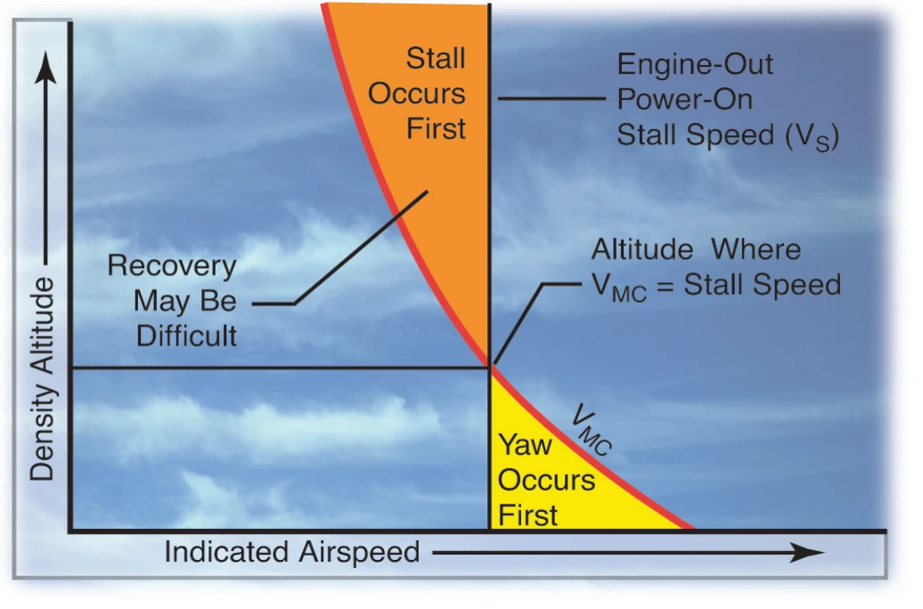
An actual demonstration of VMC may not be possible under certain conditions of density altitude, or with airplanes whose VMC is equal to or less than VS. Under those circumstances, as a training technique, a demonstration of VMC may safely be conducted by artificially limiting rudder travel to simulate maximum available rudder. A speed well above VS (approximately 20 knots) is recommended when limiting rudder travel.
The rudder limiting technique avoids the hazards of spinning as a result of stalling with high asymmetrical power, yet is effective in demonstrating the loss of directional control.
To reduce the risk of a loss of control, avoid performing any VMC demonstration from a high pitch attitude with both engines operating and then reducing power on one engine.
OEI Climb Performance
Best OEI climb performance is obtained at VYSE with maximum available power and minimum drag. After the flaps and landing gear have been retracted and the propeller of the failed engine feathered, a key element in best climb performance is minimizing sideslip.
For any airplane, sideslip can be confirmed through the use of a yaw string. A yaw string is a piece of string or yarn approximately 18 to 36 inches in length taped to the base of the windshield or to the nose near the windshield along the airplane centerline. In two-engine coordinated flight, the relative wind causes the string to align itself with the longitudinal axis of the airplane, and it positions itself straight up the center of the windshield. This is zero sideslip. Experimentation with slips and skids vividly displays the location of the relative wind. A particular combination of aileron and rudder also establishes zero sideslip during OEI flight. Adequate altitude, flying speed, and caution should be maintained if attempting these maneuvers.
With a single-engine airplane or a multiengine airplane with both engines operative, sideslip is eliminated when the ball of the turn and bank instrument is centered. This is a condition of zero sideslip, and the airplane is presenting its smallest possible profile to the relative wind. As a result, drag is at its minimum. Pilots know this as coordinated flight.
In a multiengine airplane with an inoperative engine, the centered ball is no longer the indicator of zero sideslip due to asymmetric thrust. In fact, there is no flight deck instrument that directly indicates conditions for zero sideslip. In the absence of a yaw string, the pilot needs to place the airplane at a predetermined bank angle and ball position. Since the AFM/POH performance charts for one engine inoperative flight were determined at zero sideslip, this technique should be used to obtain the charted OEI performance. There are two different control inputs that can be used to counteract the asymmetric thrust of a failed engine:
- Yaw from the rudder
- The horizontal component of lift that results from bank with the ailerons
Used individually, neither is correct. Used together in the proper combination, zero sideslip and best climb performance are achieved.
Three different scenarios of airplane control inputs are presented below. The first two are not correct and can increase the risk of a loss of control. They are presented to illustrate the reasons for the zero sideslip approach to best climb performance.
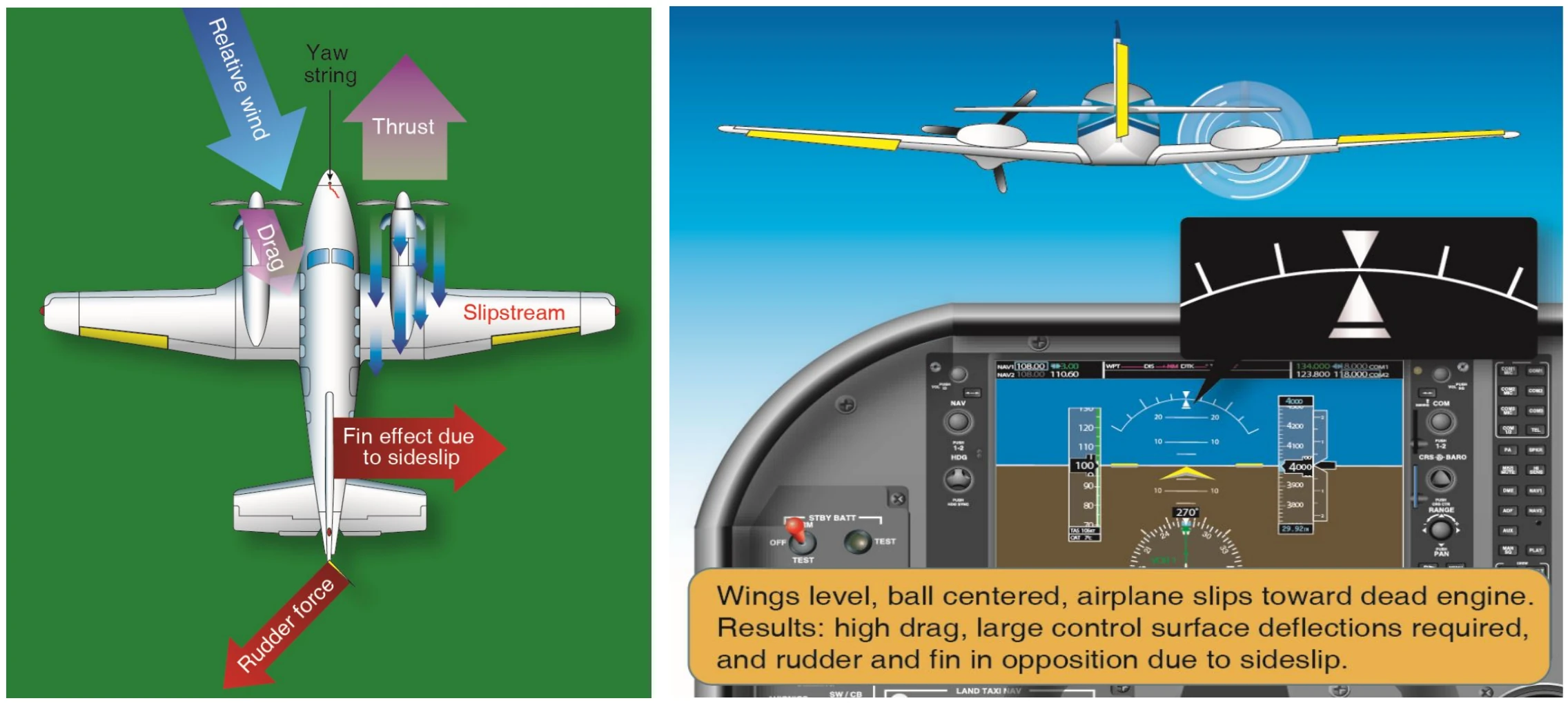
1. Engine inoperative flight with wings level and ball centered requires large rudder input toward the operative engine. [Figure 13-15] The result is a moderate sideslip toward the inoperative engine. Climb performance is reduced by the moderate sideslip. With wings level, VMC is significantly higher than published as there is no horizontal component of lift available to help the rudder combat asymmetrical thrust.
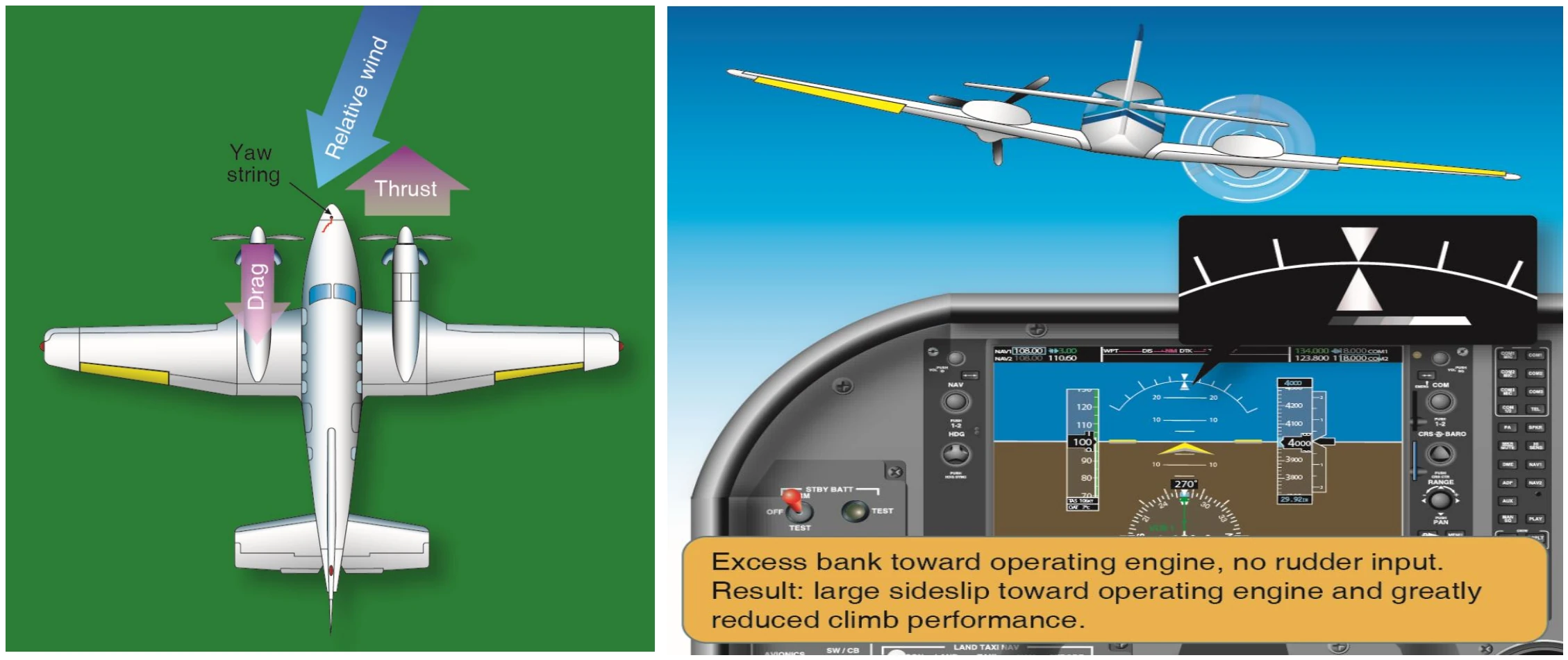
2. Engine inoperative flight using ailerons alone requires an 8–10° bank angle toward the operative engine. [Figure 13-16] This assumes no rudder input, the ball is displaced well toward the operative engine, and climb performance is greatly reduced by the large sideslip toward the operative engine. Due to the increased risk of loss of control, instructors should not normally demonstrate this.
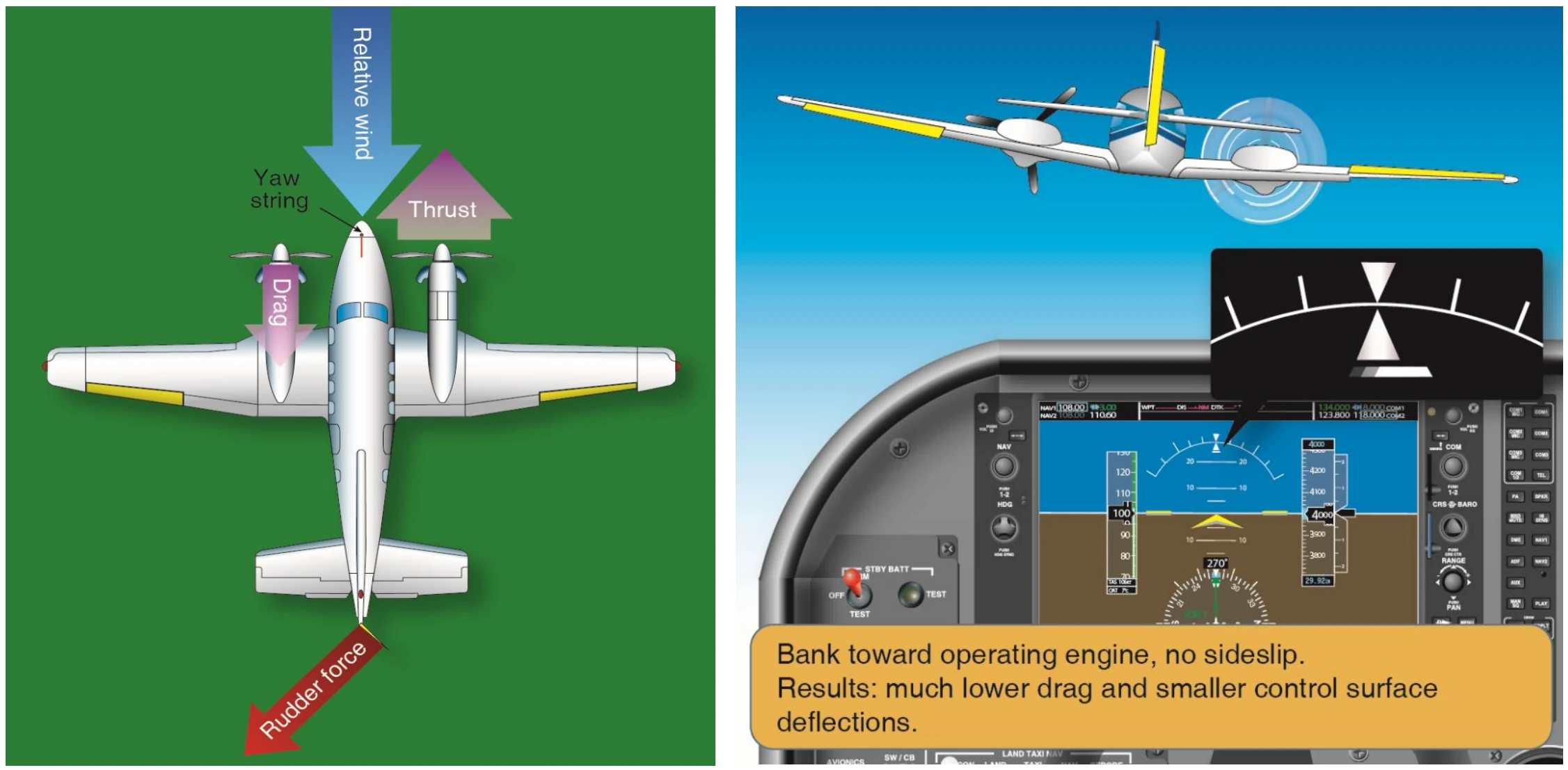
3. Rudder and ailerons used together in the proper combination result in a bank of approximately 2° toward the operative engine. The ball is displaced approximately one-third to one-half toward the operative engine. The result is zero sideslip and maximum climb performance. [Figure 13-17] Any attitude other than zero sideslip increases drag, decreasing performance. VMC under these circumstances is higher than published, as less than the 5° bank certification limit is employed.
When bank angle is plotted against climb performance for a hypothetical twin, zero sideslip results in the best (however marginal) climb performance or the least rate of descent. Whether the airplane can climb depends on the weight of the airplane, density altitude, and pilot technique. If the pilot uses zero bank (all rudder to counteract yaw), climb performance degrades as a result of moderate sideslip. Using bank angle alone (no rudder) severely degrades climb performance as a result of a large sideslip.