Chapter 10
Aircraft Systems
The principle parts of the electrical resistance thermometer are the indicating instrument, the temperature-sensitive element (or bulb), and the connecting wires and plug connectors. Electrical resistance thermometers are used widely in many types of aircraft to measure carburetor air, oil, free air temperatures, and more. They are used to measure low and medium temperatures in the –70 °C to 150 °C range.
For most metals, electrical resistance changes as the temperature of the metal changes. This is the principle upon which a resistance thermometer operates. Typically, the electrical resistance of a metal increases as the temperature rises. Various alloys have a high temperature-resistance coefficient, meaning their resistance varies significantly with temperature. This can make them suitable for use in temperature sensing devices. The metal resistor is subjected to the fluid or area in which temperature needs to be measured. It is connected by wires to a resistance measuring device inside the flight deck indicator. The instrument dial is calibrated in degrees Fahrenheit or Celsius as desired rather than in ohms. As the temperature to be measured changes, the resistance of the metal changes and the resistance measuring indicator shows to what extent.
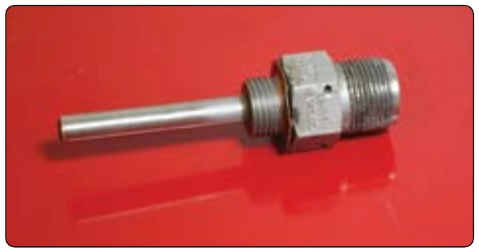
A typical electrical resistance thermometer looks like any other temperature gauge. Indicators are available in dual form for use in multiengine aircraft. Most indicators are self-compensating for changes in flight deck temperature. The heat-sensitive resistor is manufactured so that it has a definite resistance for each temperature value within its working range. The temperature-sensitive resistor element is a length or winding made of a nickel/manganese wire or other suitable alloy in an insulating material. The resistor is protected by a closed-end metal tube attached to a threaded plug with a hexagonal head. [Figure 10-68] The two ends of the winding are brazed, or welded, to an electrical receptacle designed to receive the prongs of the connector plug.
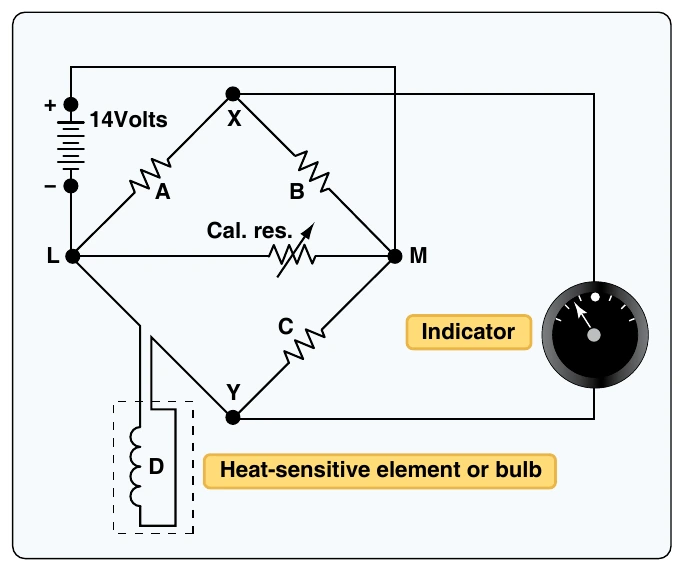
The indicator contains a resistance-measuring instrument. Sometimes it uses a modified form of the Wheatstone-bridge circuit. The Wheatstone-bridge meter operates on the principle of balancing one unknown resistor against other known resistances. A simplified form of a Wheatstone-bridge circuit is shown in Figure 10-69. Three equal values of resistance [Figure 10-69A, B, and C] are connected into a diamond shaped bridge circuit. A resistor with an unknown value [Figure 10-69D] is also part of the circuit. The unknown resistance represents the resistance of the temperature bulb of the electrical resistance thermometer system. A galvanometer is attached across the circuit at points X and Y.
When the temperature causes the resistance of the bulb to equal that of the other resistances, no potential difference exists between points X and Y in the circuit. Therefore, no current flows in the galvanometer leg of the circuit. If the temperature of the bulb changes, its resistance also changes, and the bridge becomes unbalanced, causing current to flow through the galvanometer in one direction or the other. The galvanometer pointer is actually the temperature gauge pointer. As it moves against the dial face calibrated in degrees, it indicates temperature. Many indicators are provided with a zero adjustment screw on the face of the instrument. This adjusts the zeroing spring tension of the pointer when the bridge is at the balance point (the position at which the bridge circuit is balanced and no current flows through the meter).
Ratiometer Electrical Resistance Thermometers
Another way of indicating temperature when employing an electric resistance thermometer is by using a ratiometer.
The Wheatstone-bridge indicator is subject to errors from line voltage fluctuation. The ratiometer is more stable and can deliver higher accuracy. As its name suggests, the ratiometer electrical resistance thermometer measures a ratio of current flows.
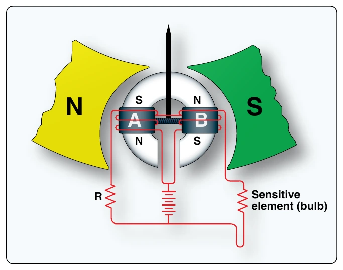
The resistance bulb sensing portion of the ratiometer electric resistance thermometer is essentially the same as described above. The circuit contains a variable resistance and a fixed resistance to provide the indication. It contains two branches for current flow. Each has a coil mounted on either side of the pointer assembly that is mounted within the magnetic field of a large permanent magnet. Varying current flow through the coils causes different magnetic fields to form, which react with the larger magnetic field of the permanent magnet. This interaction rotates the pointer against the dial face that is calibrated in degrees Fahrenheit or Celsius, giving a temperature indication. [Figure 10-70]
The magnetic pole ends of the permanent magnet are closer at the top than they are at the bottom. This causes the magnetic field lines of flux between the poles to be more concentrated at the top. As the two coils produce their magnetic fields, the stronger field interacts and pivots downward into the weaker, less concentrated part of the permanent magnet field, while the weaker coil magnetic field shifts upward toward the more concentrated flux field of the large magnet. This provides a balancing effect that changes but stays in balance as the coil field strengths vary with temperature and the resultant current flowing through the coils.
For example, if the resistance of the temperature bulb is equal to the value of the fixed resistance (R), equal values of current flow through the coils. The torques, caused by the magnetic field each coil creates, are the same and cancel any movement in the larger magnetic field. The indicator pointer will be in the vertical position. If the bulb temperature increases, its resistance also increases. This causes the current flow through coil A circuit branch to increase. This creates a stronger magnetic field at coilA than at coil B. Consequently, the torque on coil A increases, and it is pulled downward into the weaker part of the large magnetic field. At the same time, less current flows through the sensor bulb resistor and coil B, causing coil B to form a weaker magnetic field that is pulled upward into the stronger flux area of the permanent magnet’s magnetic field. The pointer stops rotating when the fields reach a new balance point that is directly related to the resistance in the sensing bulb. The opposite of this action would take place if the temperature of the heat-sensitive bulb should decrease.
Ratiometer temperature measuring systems are used to measure engine oil, outside air, carburetor air, and other temperatures in many types of aircraft. They are especially in demand to measure temperature conditions where accuracy is important, or large variations of supply voltages are encountered.
Thermocouple Temperature Indicators
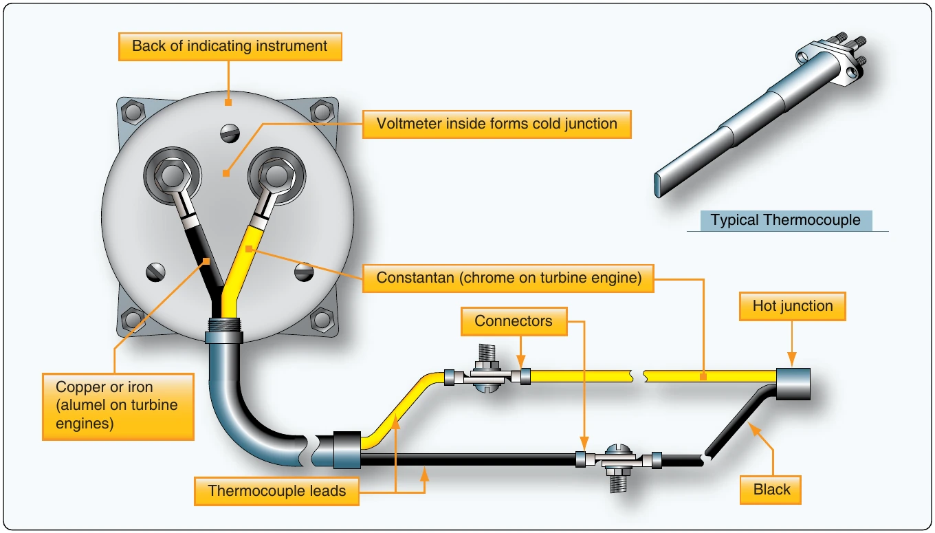
A thermocouple is a circuit or connection of two unlike metals. The metals are touching at two separate junctions. If one of the junctions is heated to a higher temperature than the other, an electromotive force is produced in the circuit. This voltage is directly proportional to the temperature. So, by measuring the amount of electromotive force, temperature can be determined. A voltmeter is placed across the colder of the two junctions of the thermocouple. It is calibrated in degrees Fahrenheit or Celsius, as needed. The hotter the high-temperature junction (hot junction) becomes, the greater the electromotive force produced, and the higher the temperature indication on the meter. [Figure 10-71]
Thermocouples are used to measure high temperatures. Two common applications are the measurement of cylinder head temperature (CHT) in reciprocating engines and exhaust gas temperature (EGT) in turbine engines. Thermocouple leads are made from a variety of metals, depending on the maximum temperature to which they are exposed. Iron and constantan, or copper and constantan, are common for CHT measurement. Chromel and alumel are used for turbine EGT thermocouples.
The amount of voltage produced by the dissimilar metals when heated is measured in millivolts. Therefore, thermocouple leads are designed to provide a specific amount of resistance in the thermocouple circuit (usually very little). Their material, length, or cross-sectional size cannot be altered without compensation for the change in total resistance that would result. Each lead that makes a connection back to the voltmeter must be made of the same metal as the part of the thermocouple to which it is connected. For example, a copper wire is connected to the copper portion of the hot junction and a constantan wire is connected to the constantan part.