
Chapter 10
Aircraft Systems
Annunciator Panels
An annunciator panel is a panel of warning lights in plain sight of the pilot. These lights are identified by the name of the system they represent and are usually covered with colored lenses to show the meaning of the condition they announce. Annunciator panels are installed for two purposes: to display current conditions and to notify of unsatisfactory conditions. Standardized colors are used to differentiate between visual messages. For example, the color green indicates a satisfactory condition. Yellow is used to caution of a serious condition that requires further monitoring. Red is the color for an unsatisfactory condition which needs immediate attention or action. Whether part of the instrument face or of a visual warning system, these colors give quick-reference information to the pilot.
Most aircraft include annunciator lights that illuminate when an event demanding attention occurs. These use the aforementioned colors in a variety of presentations. Individual lights near the associated flight deck instrument or a collective display of lights for various systems in a central location are common. Words label each light or are part of the light itself to identify any problem quickly and plainly.
On complex aircraft, the status of numerous systems and components must be known and maintained. Centralized warning systems have been developed to annunciate critical messages concerning a multitude of systems and components in a simplified, organized manner. Often, this will be done by locating a single annunciator panel somewhere on the instrument panel. These analog aircraft warning systems may look different in various aircraft and depend on manufacturer preference and the systems installed. [Figure 10-128] EFIS provide for annunciation of advisory and warning messages as part of its flight control and monitoring capabilities, as previously described. Usually, the primary display unit is designated as the location to display annunciations.
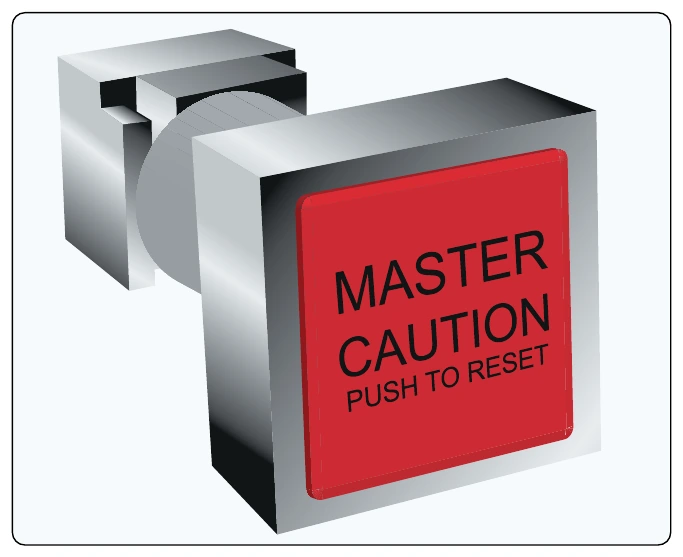
Master caution lights are used to draw the attention of the crew to a critical situation in addition to an annunciator that describes the problem. These master caution lights are centrally wired and illuminate whenever any of the participating systems or components require attention. Once notified, the pilot may cancel the master caution, but a dedicated system or component annunciator light stays illuminated until the situation that caused the warning is rectified. Cancelling resets the master caution lights to warn of a subsequent fault event even before the initial fault is corrected. [Figure 10-129] Press to test is available for the entire annunciator system, which energizes all warning circuitry and lights to confirm readiness. Often, this test exposes the need to replace the tiny light bulbs that are used in the system.
Aural Warning Systems
Aircraft aural warning systems work in conjunction with illuminated annunciator systems. They audibly inform the pilot of a situation requiring attention. Various tones and phrases sound in the flight deck to alert the crew when certain conditions exist. For example, an aircraft with retractable landing gear uses an aural warning system to alert the crew to an unsafe condition. A bell sounds if the throttle is retarded and the landing gear is not in a down and locked condition.
A typical transport category aircraft has an aural warning system that alerts the pilot with audio signals for the following: abnormal takeoff, landing, pressurization, mach airspeed conditions, an engine or wheel well fire, calls from the crew call system, collision avoidance recommendations, and more. Figure 10-130 shows some of the problems that trigger aural warnings and the action to be taken to correct the situation.
Clocks
Whether called a clock or a chronometer, an FAA-approved time indicator is required in the flight deck of IFR-certified aircraft. Pilots use a clock during flight to time maneuvers and for navigational purposes. The clock is usually mounted near the flight instrument group, often near the turn coordinator. It indicates hours, minutes, and seconds.
For many years, the mechanical 8-day clock was the standard aircraft timekeeping device largely because it continues to run without electrical power as long as it has been hand wound. The mechanical 8-day clock is reliable and accurate enough for its intended use. Some mechanical aircraft clocks feature a push-button elapsed time feature. [Figure 10-131]
As electrical systems developed into the reliable, highly redundant systems that exist today, use of an electric clock to replace the mechanical clock began. An electric clock is an analog devise that may also have an elapsed time feature. It can be wired to the battery or battery bus. Thus, it continues to operate in the event of a power failure. Electric aircraft clocks are often used in multiengine aircraft where complete loss of electrical power is unlikely.
Many modern aircraft have a digital electronic clock with LED readout. This device comes with the advantages of low power consumption and high reliability due to the lack of moving parts. It is also very accurate. Solid-state electronics allow for expanded features, such as elapsed time, flight time that starts automatically upon takeoff, a stop watch, and memories for all functions. Some even have temperature and date readouts. Although wired into the aircraft’s electrical system, electronic digital clocks may include a small independent battery inside the unit that operates the device should aircraft electrical power fail. [Figure 10-132]
On aircraft with fully digital computerized instrument systems utilizing flat panel displays, the computer’s internal clock, or a GPS clock, can be used with a digital time readout usually located somewhere on the primary flight display.
Instrument Housings & Handling
Various materials are used to protect the inner workings of aircraft instruments, as well as to enhance the performance of the instrument and other equipment mounted in the immediate vicinity. Instrument cases can be one piece or multipiece. Aluminum alloy, magnesium alloy, steel, iron, and plastic are all common materials for case construction. Electric instruments usually have a steel or iron alloy case to contain electromagnetic flux caused by current flow inside.