Chapter 10
Aircraft Systems
Engine Indicating & Crew Alerting System (EICAS)
An engine indicating and crew alerting system (EICAS) performs many of the same functions as an ECAM system. The objective is still to monitor the aircraft systems for the pilot. All EICASs display engine, as well as airframe, parameters.
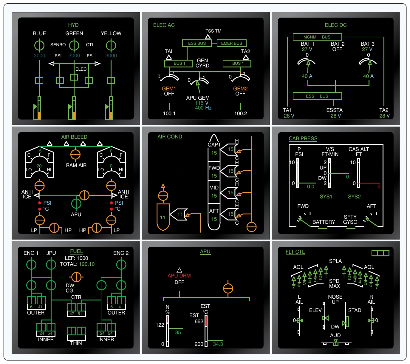
Traditional gauges are not utilized, other than as a standby combination engine gauge in case of total system failure.
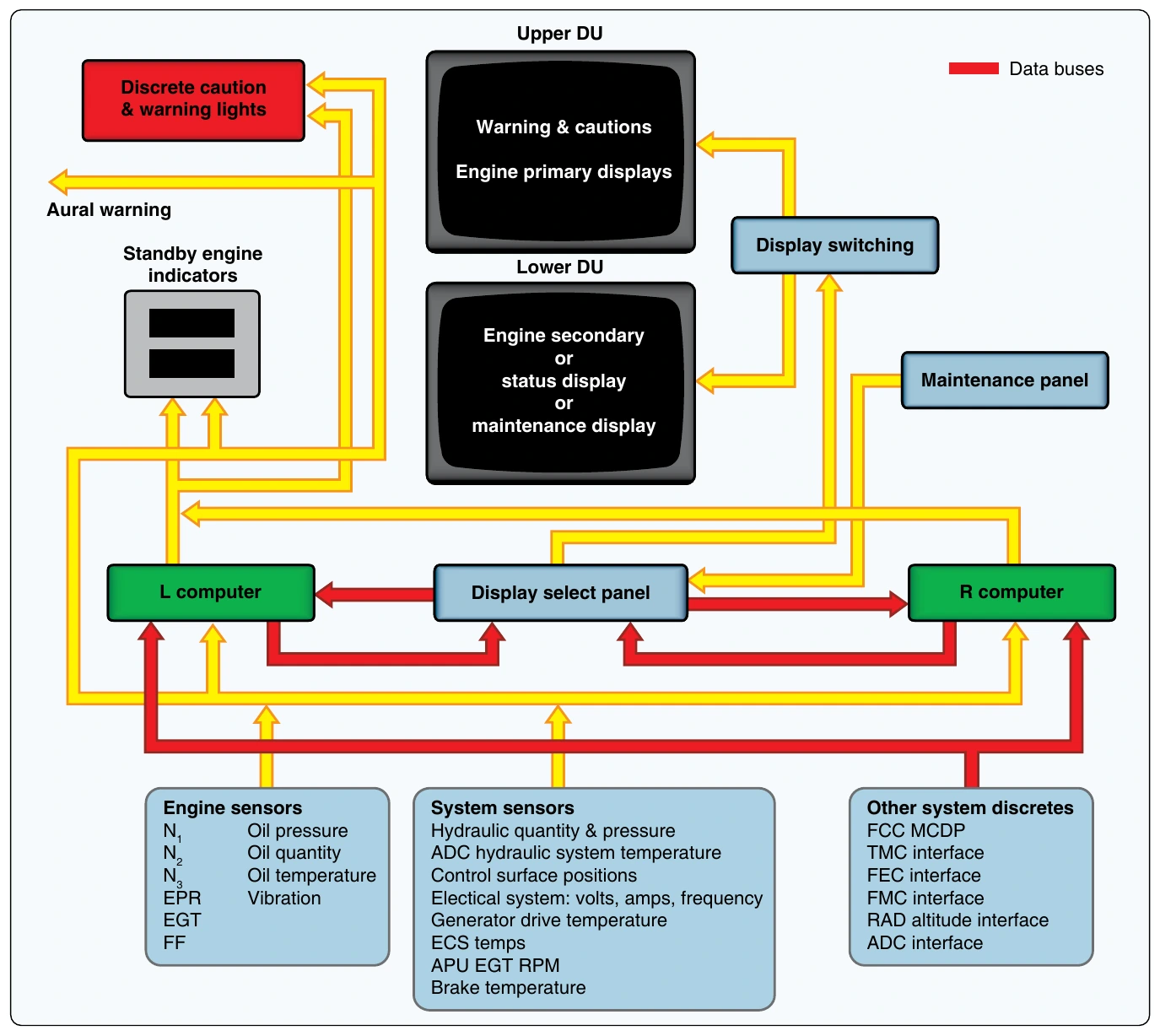
EICAS is also a two-monitor, two-computer system with a display select panel. Both monitors receive information from the same computer. The second computer serves as a standby. Digital and analog inputs from the engine and airframe systems are continuously monitored. Caution and warning lights, as well as aural tones, are incorporated. [Figure 10-124]
EICAS provides full time primary engine parameters (EPR, N1, EGT) on the top, primary monitor. Advisories and warning are also shown there. Secondary engine parameters and nonengine system status are displayed on the bottom screen. The lower screen is also used for maintenance diagnosis when the aircraft is on the ground. Color coding is used, as well as message prioritizing.
The display select panel allows the pilot to choose which computer is actively supplying information. It also controls the display of secondary engine information and system status displays on the lower monitor. EICAS has a unique feature that automatically records the parameters of a failure event to be reviewed afterwards by maintenance personnel. Pilots that suspect a problem may be occurring during flight can press the event record button on the display select panel. This also records the parameters for that flight period to be studied later by maintenance. Hydraulic, electrical, environmental, performance, and APU data are examples of what may be recorded.
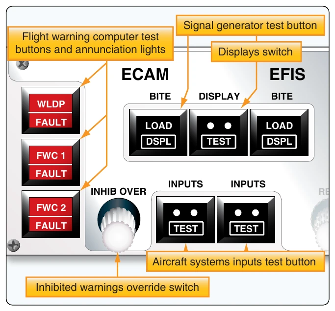
EICAS uses BITE for systems and components. A maintenance panel is included for technicians. From this panel, when the aircraft is on the ground, push-button switches display information pertinent to various systems for analysis. [Figure 10-125]
Flight Management System (FMS)
The highest level of automated flight system is the flight FMS. Companies flying aircraft for hire have special results they wish to achieve. On-time performance, fuel conservation, and long engine and component life all contribute to profitability. An FMS helps achieve these results by operating the aircraft with greater precision than possible by a human pilot alone.
A FMS can be thought of as a master computer system that has control over all other systems, computerized and otherwise. As such, it coordinates the adjustment of flight, engine, and airframe parameters either automatically or by instructing the pilot how to do so. Literally, all aspects of the flight are considered, from preflight planning to pulling up to the jet-way upon landing, including in-flight amendments to planned courses of action.
The main component of an FMS is the flight management computer (FMC). It communicates with the EICAS or ECAM, the ADC, the thrust management computer that controls the autothrottle functions, the EIFIS symbol generators, the automatic flight control system, the inertial reference system, collision avoidance systems, and all of the radio navigational aids via data busses. [Figure 10-126]
The interface to the system is a control display unit (CDU) that is normally located forward on the center pedestal in the flight deck. It contains a full alphanumeric keypad, a CRT or LCD display/work screen, status and condition annunciators, and specialized function keys. [Figure 10-127]
The typical FMS uses two FMS FMCs that operate independently as the pilot’s unit and the copilot’s unit. However, they do crosstalk through the data busses. In normal operation, the pilot and copilot divide the workload, with the pilot’s CDU set to supervise and interface with operational parameters and the copilot’s CDU handling navigational Tchores. This is optional at the flightcrew’s discretion. If a main component fails (e.g., an FMC or a CDU), the remaining operational units continue to operate with full control and without system compromise.
Each flight of an aircraft has vertical, horizontal, and navigational components, which are maintained by manipulating the engine and airframe controls. While doing so, numerous options are available to the pilot. Rate of climb, thrust settings, EPR levels, airspeed, descent rates, and other terms can be varied. Commercial air carriers use the FMC to establish guidelines by which flights can be flown. Usually, these promote the company’s goals for fuel and equipment conservation. The pilot need only enter variables as requested and respond to suggested alternatives as the FMC presents them.
The FMC has stored in its database literally hundreds of flight plans with predetermined operational parameters that can be selected and implemented. Integration with NAV-COM aids allows the FMS to change radio frequencies as the flight plan is enacted. Internal computations using direct input from fuel flow and fuel quantity systems allow the FMC to carry out lean operations or pursue other objectives, such as high performance operations if making up time is paramount on a particular flight. Weather and traffic considerations are also integrated. The FMS can handle all variables automatically but communicates via the CDU screen to present its planned action, gain consensus, or ask for an input or decision.
As with the monitoring systems, FMS includes BITE. The FMC continuously monitors its entire systems and inputs for faults during operation. Maintenance personal can retrieve system generated and pilot recorded fault messages. They may also access maintenance pages that call out line replaceable units (LRUs) to which faults have been traced by the BITE system. Follow manufacturers’ procedures for interfacing with maintenance data information.