
Chapter 11
Communication & Navigation
Oscillators function to make AC from DC. They can produce various waveforms as required by electronic circuits. There are many different types of oscillators and oscillator circuits. Some of the most common types are discussed below.
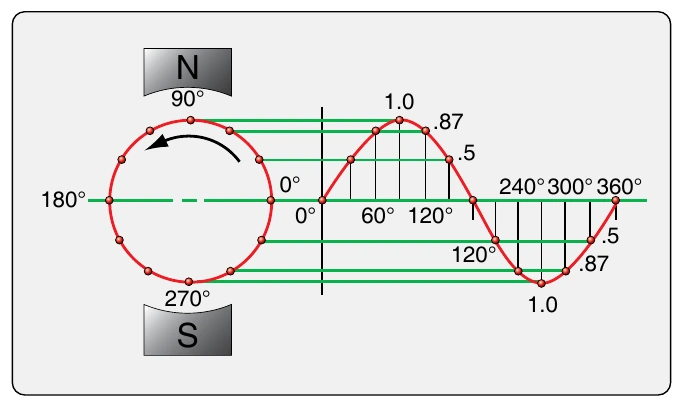
A sine wave is produced by generators when a conductor is rotated in a uniform magnetic field. The typical AC sine wave is characterized by a gradual build-up and decline of voltage in one direction, followed by a similar smooth build-up to peak voltage and decline to zero again in the opposite direction. The value of the voltage at any given time in the cycle can be calculated by taking the peak voltage and multiplying it by the sine of the angle through which the conductor has rotated. [Figure 11-55]
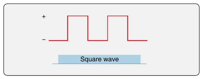
A square wave is produced when there is a flow of electrons for a set period that stops for a set amount of time and then repeats. In DC current, this is simply pulsing DC. [Figure 11-56] This same wave form can be of opposite polarities when passed through a transformer to produce AC. Certain oscillators produce square waves.
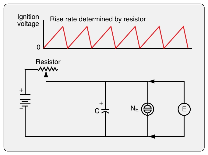
An oscillator known as a relaxation oscillator produces another kind of wave form, a sawtooth wave. A slow rise from zero to peak voltage is followed by a rapid drop-off of voltage back to almost zero. Then it repeats. [Figure 11-57] In the circuit, a capacitor slowly charges through a resistor. A neon bulb is wired across the capacitor. When its ignition voltage is reached, the bulb conducts. This short-circuits the charged capacitor, which causes the voltage to drop to nearly zero and the bulb goes out. Then, the voltage rises again as the cycle repeats.
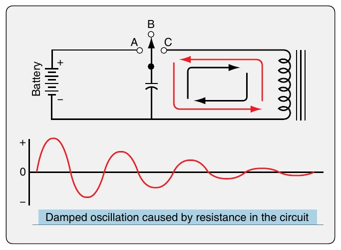
Electronic Oscillation Oscillation in electronic circuits is accomplished by combining a transistor and a tank circuit. A tank circuit is comprised of a capacitor and coil parallel to each other. [Figure 11-58] When attached to a power source by closing switch A, the capacitor charges to a voltage equal to the battery voltage. It stays charged, even when the circuit to the battery is open (switch in position B). When the switch is put in position C, the capacitor and coil are in a closed circuit. The capacitor discharges through the coil. While receiving the energy from the capacitor, the coil stores it by building up an electromagnetic field. When the capacitor is fully discharged, the coil stops conducting. The magnetic field collapses, which induces current flow. The current charges the opposite plate of the capacitor. When completely charged, the capacitor discharges into the coil again. The magnetic field builds again and stops when the capacitor is fully discharged. The magnetic field collapses again, which induces current that charges the original plate of the capacitor and the cycle repeats.
This oscillation of charging and discharging the capacitor through the coil would continue indefinitely if a circuit could be built with no resistance. This is not possible. However, a circuit can be built using a transistor that restores losses due to resistance. There are various ways to accomplish this. The Hartley oscillator circuit in Figure 11-59 is one. The circuit can oscillate indefinitely as long as it is connected to power.
When the switch is closed, current begins to flow in the oscillator circuit. The transistor base is supplied with biasing current through the voltage divider RA and RB. This allows current to flow through the transistor from the collector to the emitter, through RE and through the lower portion of the center tapped coil that is labeled L1. The current increasing through this coil builds a magnetic field that induces current in the upper half of the coil labeled L2. The current from L2 charges capacitor C2, which increases the forward bias of the transistor. This allows an increasing flow of current through the transistor, RE, and L1 until the transistor is saturated and capacitor C1 is fully charged. Without force to add electrons to capacitor C1, it discharges and begins the oscillation in the tank circuit described in the previous section. As C1 becomes fully charged, current to charge C2 reduces and C2 also discharges. This adds the energy needed to the tank circuit to compensate for resistance losses. As C2 is discharging, it reduces forward biasing and eventually the transistor becomes reversed biased and cuts off. When the opposite plate of capacitor C1 is fully charged, it discharges, and the oscillation is in progress. The transistor base becomes forward biased again, allowing for current flow through the resistor RE, coil L1, etc.
The frequency of the AC oscillating in the Hartley oscillator circuit depends on the inductance and capacitance values of the components used. Use of a crystal in an oscillator circuit can control the frequency more accurately. A crystal vibrates at a single, consistent frequency. When flexed, a small pulse of current is produced through the piezoelectric effect. Placed in the feedback loop, the pulses from the crystal control the frequency of the oscillator circuit. The tank circuit component values are tuned to match the frequency of the crystal. Oscillation is maintained as long as power is supplied. [Figure 11-60]
Other types of oscillator circuits used in electronics and computers have two transistors that alternate being in the active mode. They are called multi-vibrators. The choice of oscillator in an electronic device depends on the exact type of manipulation of electricity required to permit the device to function as desired.