
Chapter 11
Communication & Navigation
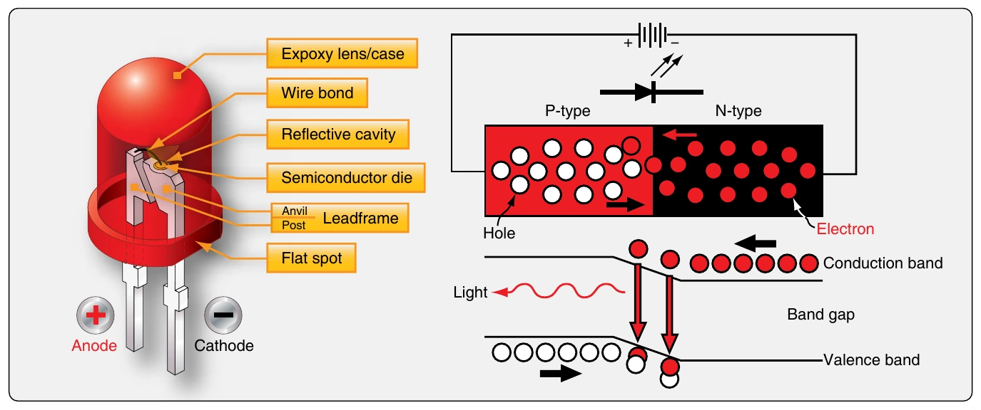
Light emitting diodes (LEDs) have become so commonly used in electronics that their importance may tend to be overlooked. Numerous avionics displays and indicators use LEDs for indicator lights, digital readouts, and backlighting of liquid crystal display (LCD) screens.
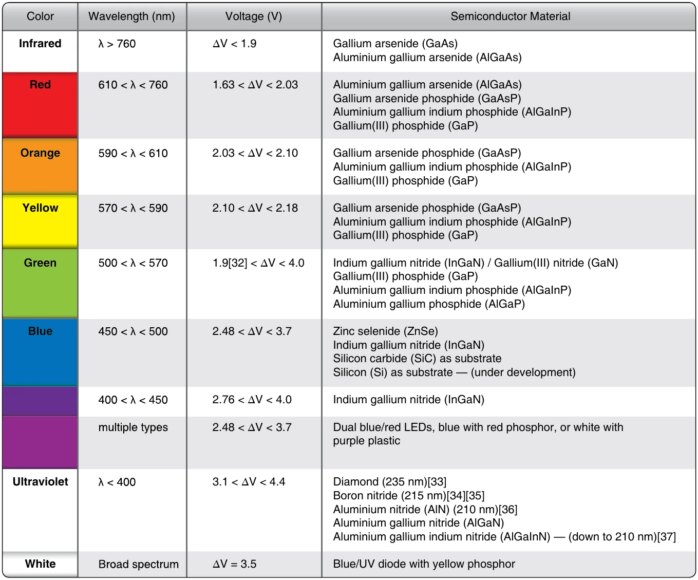
LEDs are simple and reliable. They are constructed of semiconductor material. When a free electron from a semiconductor drops into a semiconductor hole, energy is given off. This is true in all semiconductor materials. However, the energy released when this happens in certain materials is in the frequency range of visible light. Figure 11-41 is a table that illustrates common LED colors and the semiconductor material that is used in the construction of the diode.
Basic Analog Circuits
The solid-state semiconductor devices described in the previous section of this chapter can be found in both analog and digital electronic circuits. As digital electronics evolve, analog circuitry is being replaced. However, many aircraft still make use of analog electronics in radio and navigation equipment, as well as in other aircraft systems. A brief look at some of the basic analog circuits follows.
Rectifiers
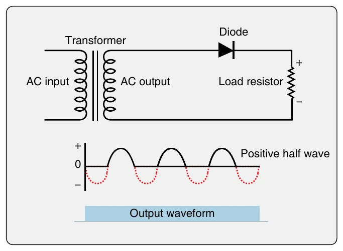
Rectifier circuits change AC voltage into DC voltage and are one of the most commonly used type of circuits in aircraft electronics. [Figure 11-43] The resulting DC waveform output is also shown. The circuit has a single semiconductor diode and a load resistor. When the AC voltage cycles below zero, the diode shuts off and does not allow current flow until the AC cycles through zero voltage again. The result is pronounced pulsating DC. While this can be useful, half of the original AC voltage is not being used.
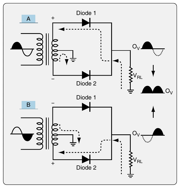
A full wave rectifier creates pulsating DC from AC while using the full AC cycle. One way to do this is to tap the secondary coil at its midpoint and construct two circuits with the load resistor and a diode in each circuit. [Figure 11-44] The diodes are arranged so that when current is flowing through one, the other blocks current.
When the AC cycles so the top of the secondary coil of the transformer is positive, current flows from ground, through the load resistor (VRL), Diode 1, and the upper half of the coil. Current cannot flow through Diode 2 because it is blocked. [Figure 11-44A] As the AC cycles through zero, the polarity of the secondary coil changes. [Figure 11-44B] Current then flows from ground, through the load resistor, Diode 2, and the bottom half of the secondary coil. Current flow through Diode 1 is blocked. This arrangement yields positive DC from cycling AC with no wasted current.
Another way to construct a full wave rectifier uses four semiconductor diodes in a bridge circuit. Because the secondary coil of the transformer is not tapped at the center, the resultant DC voltage output is twice that of the two-diode full wave rectifier. [Figure 11-45] During the first half of the AC cycle, the bottom of the secondary coil is negative. Current flows from it through diode (D1), then through the load resistor, and through diode (D2) on its way back to the top of the secondary coil. When the AC reverses its cycle, the polarity of the secondary coil changes. Current flows from the top of the coil through diode (D3), then through the load resistor, and through diode (D4) on its way back to the bottom of the secondary coil. The output waveform reflects the higher voltage achieved by rectifying the full AC cycle through the entire length of the secondary coil.
Use and rectification of three-phase AC is also possible on aircraft with a specific benefit. The output DC is very smooth and does not drop to zero. A six-diode circuit is built to rectify the typical three-phase AC produced by an aircraft alternator. [Figure 11-46]
Each stator coil corresponds to a phase of AC and becomes negative for 120° of rotation of the rotor. When stator 1 or the first phase is negative, current flows from it through diode (D1), then through the load resistor and through diode (D2) on its way back to the third phase coil. Next, the second phase coil becomes negative and current flows through diode (D3). It continues to flow through the load resistor and diode (D4) on its way back to the first phase coil. Finally, the third stage coil becomes negative causing current to flow through diode (D5), then the load resistor and diode (D6) on its way back to the second phase coil. The output waveform of this three-phase rectifier depicts the DC produced. It is a relatively steady, non-pulsing flow equivalent to just the tops of the individual curves. The phase overlap prevents voltage from falling to zero producing smooth DC from AC.
Amplifiers
An amplifier is a circuit that changes the amplitude of an electric signal. This is done through the use of transistors. As mentioned, a transistor that is forward biased at the base-emitter junction and reversed biased at the collector-base junction is turned on. It can conduct current from the collector to the emitter. Because a small signal at the base can cause a large current to flow from collector to emitter, a transistor in itself can be said to be an amplifier. However, a transistor properly wired into a circuit with resistors, power sources, and other electronic components, such as capacitors, can precisely control more than signal amplitude. Phase and impedance can also be manipulated.