Chapter 11
Communication & Navigation
Since the typical bipolar junction transistor requires a based circuit and a collector-emitter circuit, there should be four terminals, two for each circuit. However, the transistor only has three terminals (i.e., the base, the collector, and the emitter). Therefore, one of the terminals must be common to both transistor circuits. The selection of the common terminal affects the output of the amplifier.
The three basic amplifier types, named for which terminal of the transistor is the common terminal to both transistor circuits, include:
- Common-emitter amplifier.
- Common-collector amplifier.
- Common-base amplifier.
Common-Emitter Amplifier
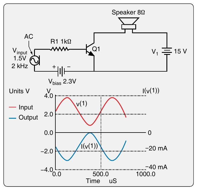
The common-emitter amplifier controls the amplitude of an electric signal and inverts the phase of the input signal. Figure 11-47 illustrates a common-emitter amplifier for AC using a NPN transistor and its output signal graph. Common emitter circuits are characterized by high current gain and a 180° voltage phase shift from input to output. It is for the amplification of a microphone signal to drive a speaker. As always, adequate voltage of the correct polarity to the base puts the transistor in the active mode or turns it on. Then, as the base input current fluctuates, the current through the transistor fluctuates proportionally. However, AC cycles through positive and negative polarity. Every 180°, the transistor shuts off because the polarity to the base-emitter junction of the transistor is not correct to forward bias the junction. To keep the transistor on, a DC biasing voltage of the correct polarity (shown as a 2.3 volts (V) battery) is placed in series with the input signal in the base circuit to hold the transistor in the active mode as the AC polarity changes. This way the transistor stays in the active mode to amplify an entire AC signal.
Transistors are rated by ratio of the collector current to the base current, or Beta (β). This is established during the manufacture of the unit and cannot be changed. A 100 β transistor can handle 100 times more current through a collector-emitter circuit than the base input signal. This current in Figure 11-47 is provided from the 15V battery, V1. So, the amplitude of amplification is a factor of the beta of the transistor and any inline resistors used in the circuits. The fluctuations of the output signal, however, are entirely controlled by the fluctuations of current input to the transistor base.
If measurements of input and output voltages are made, it is shown that as the input voltage increases, the output voltage decreases. This accounts for the inverted phase produced by a common-emitter circuit. [Figure 11-47]
Common-Collector Amplifier
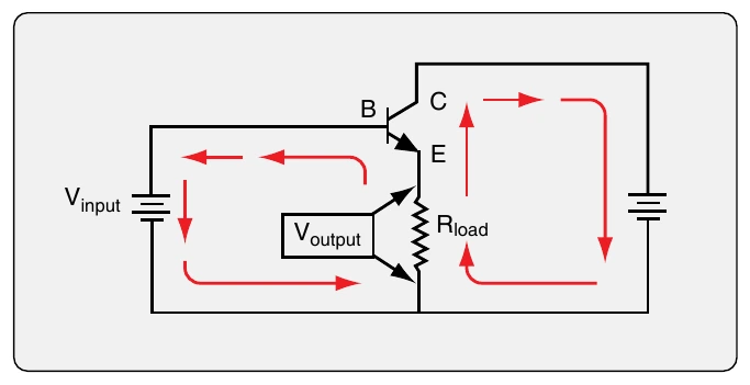
Another basic type of amplifier circuit is the common-collector amplifier. Common-collector circuits are characterized by high current gain, but virtually no voltage gain. The input circuit and the load circuit in this amplifier share the collector terminal of the transistor used. Because the load is in series with the emitter, both the input current and output current run through it. This causes a directly proportional relationship between the input and the output. The current gain in this circuit configuration is high. A small amount of input current can control a large amount of current to flow from the collector to the emitter. A common collector amplifier circuit is illustrated in Figure 11-48. The base current needs to flow through the PN junction of the transistor, which has about a 0.7V threshold to be turned on. The output current of the amplifier is the beta value of the transistor plus 1.
DuringAC amplification, the common-collector amplifier has the same problem that exists in the common-emitter amplifier. The transistor must stay on or in the active mode regardless of input signal polarity. When the AC cycles through zero, the transistor turns off because the minimum amount of current to forward bias the transistor is not available. The addition of a DC biasing source (battery) in series with the AC signal in the input circuit keeps the transistor in the active mode throughout the full AC cycle. [Figure 11-49]
A common-collector amplifier can also be built with a PNP transistor. [Figure 11-50] It has the same characteristics as the NPN common-collector amplifier shown in Figure 11-50. When arranged with a high resistance in the input circuit and a small resistance in the load circuit, the common-collector amplifier can be used to step down the impedance of a signal. [Figure 11-51]
Common-Base Amplifier
A third type of amplifier circuit using a bipolar transistor is the common-base amplifier. In this circuit, the shared transistor terminal is the base terminal. [Figure 11-52] This causes a unique situation in which the base current is actually larger than the collector or emitter current. As such, the common-base amplifier does not boost current as the other amplifiers do. It attenuates current but causes a high gain in voltage. A very small fluctuation in base voltage in the input circuit causes a large variation in output voltage. The effect on the circuit output is direct, so the output voltage phase is the same as the input signal but much greater in amplitude.
As with the other amplifier circuits, when amplifying an AC signal with a common-base amplifier circuit, the input signal to the base must include a DC source to forward bias the transistor’s base-emitter junction. This allows current to flow from the collector to the emitter during both cycles of the AC. A circuit for AC amplification is illustrated in Figure 11-53 with a graph of the output voltage showing the large increase produced. The common-base amplifier is limited in its use since it does not increase current flow. This makes it the least used configuration. However, it is used in radio frequency amplification because of the low input Z. Figure 11-54 summarizes the characteristics of the bipolar amplifier circuits discussed above.