
Chapter 11
Communication & Navigation
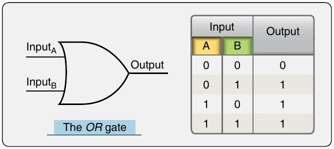
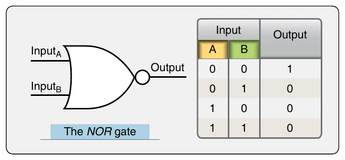
NOR Gate A NOR gate is similarly arranged except that it is an inverted OR gate. If there is to be a Logic 1 output, or output voltage, then neither input can be Logic 1 or have input voltage. This is the same as satisfying the OR gate conditions and then putting output through a NOT gate. The NOR gate truth table in Figure 11-67 shows that the NOR gate output values are exactly the opposite of the OR gate output values.
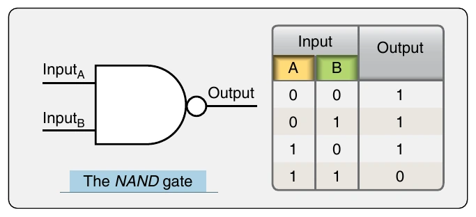
The NAND gate and the NOR gate have a unique distinction. Each one can be the only gate used in circuitry to produce the same output as any of the other logic gates. While it may be inefficient, it is testimonial to the flexibility that designers have when working with logic gates, the NAND and NOR gates in particular.
EXCLUSIVE OR Gate Another common logic gate is the EXCLUSIVE OR gate. It is the same as an OR gate except for the condition where both inputs are Logic 1. In an OR gate, there would be Logic
1 output when both inputs are Logic 1. This is not allowed
in an EXCLUSIVE OR gate. When either of the inputs is Logic 1, the output is Logic 1. But, if both inputs are logic 1, the Logic 1 output is excluded or Logic 0. [Figure 11-68]
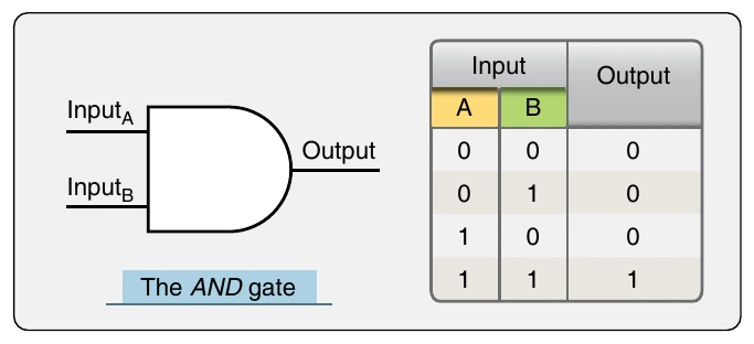
Negative Logic Gates There are also negative logic gates. The negative OR and the negative AND gates are gates wherein the inputs are inverted rather than inverting the output. This creates a unique set of outputs as seen in the truth tables in Figure 11-69. The negative OR gate is not the same as the NOR gate as is sometimes misunderstood. Neither is the negative AND gate the same as the NAND gate. However, as the truth tables reveal, the output of a negative AND gate is the same as a NOR gate, and the output of a negative OR gate is the same as a NAND gate.
In summary, electronic circuits use transistors to construct logic gates that produce outputs related to the inputs shown in the truth tables for each kind of gate. The gates are then assembled with other components to manipulate data in digital circuits. The electronic digital signals used are voltage or no voltage representations of Logic 1 or Logic 0 conditions. By using a series of voltage output or no voltage output gates, manipulation, computation, and storage of data takes place.
Digital Aircraft Systems
Digital aircraft systems are the present and future of aviation. From communication and navigation to engine and flight controls, increased proliferation of digital technology increases reliability and performance. Processing, storing, and transferring vital information for the operation of an aircraft in digital form provides a usable common language
for monitoring, control, and safety. Integration of information from different systems is simplified. Self-monitoring, built-in test equipment (BITE) and air-to-ground data links increase maintenance efficiency. Digital buss networking allows aircraft system computers to interact for a coordinated comprehensive approach to flight operations.