
Chapter 11
Communication & Navigation
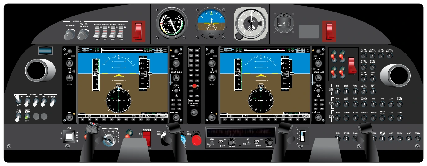
Modern digital data displays are the most visible features of digital aircraft systems. They extend the functional advantages of state of the art digital communication and navigation avionics and other digital aircraft systems via the use of an enhanced interface with the pilot. The result is an increase in situational awareness and overall safety of flight. Digital data displays are the glass of the glass flight deck. They expand the amount, clarity, and proximity of the information presented to the pilot. [Figure 11-70]
Many digital data displays are available from numerous manufacturers as original equipment in new aircraft, or as retrofit components or complete retrofit systems for older aircraft. Approval for retrofit displays is usually accomplished through supplementary type certificate (STC) awarded to the equipment manufacturer.
Early digital displays presented scale indication in digital or integer format readouts. Today’s digital data displays are analogous to computer screen presentations. Numerous aircraft and flight instrument readouts and symbolic presentations are combined with communication and navigational information on multifunctional displays (MFD).
Often a display has a main function with potential to back-up another display should it fail. Names, such as primary flight display (PFD), secondary flight display, navigational display (ND), etc., are often used to describe a display by its primary use. The hardware composition of the displays is essentially the same. Avionics components and computers combine to provide the different information portrayed on the displays.
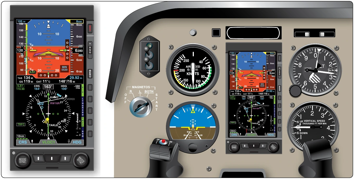
Controls on the instrument panel or on the display unit itself are used for selection. Some screens have limited display capability because they are not part of a totally integrated system; however, they are extremely powerful electronic units with wide capability. [Figure 11-71]
The basis of the information displayed on what is known as a PFD, is usually an electronic flight instrument system (EFIS) like representation of the aircraft attitude indicator in the upper half of the display, and an electronic horizontal situation indicator display on the lower half. Numerous ancillary readouts are integrated or surround the electronic attitude indicator and the horizontal situation indicator (HSI). On full glass flight deck PFDs, all of the basic T instrument indications are presented and much more, such as communication and navigation information, weather data, terrain features, and approach information. Data displays for engine parameters, hydraulics, fuel, and other airframe systems are often displayed on the secondary flight display or on an independent display made for this purpose. [Figure 11-72]
As with other avionics components, repair and maintenance of the internal components of digital data displays is reserved for licensed repair stations only.
Digital Tuners & Audio Panels
Numerous communication and navigation devices are described in the following sections of this chapter. Many of these use radio waves and must be tuned to a desired frequency for operation. As a flight progresses, retuning and changing from one piece of equipment to another can occur frequently. An audio panel or digital tuner consolidates various communication and navigation radio selection controls into a single unit. The pilot can select and use, or select and tune, most of the aircraft’s avionics from this one control interface. [Figure 11-73]
Radio Communication
Much of aviation communication and navigation is accomplished through the use of radio waves. Communication by radio was the first use of radio frequency transmissions in aviation.
Radio Waves
A radio wave is invisible to the human eye. It is electromagnetic in nature and part of the electronic spectrum of wave activity that includes gamma rays, x-rays, ultraviolet rays, infrared waves, and visible light rays, as well all radio waves. [Figure 11-74] The atmosphere is filled with these waves. Each wave occurs at a specific frequency and has a corresponding wavelength. The relationship between frequency and wavelength is inversely proportional. A high frequency wave has a short wavelength and a low frequency wave has a long wavelength.
In aviation, a variety of radio waves are used for communication. Figure 11-75 illustrates the radio spectrum that includes the range of common aviation radio frequencies and their applications.