
Chapter 11
Communication & Navigation
AC power of a particular frequency has a characteristic length of conductor that is resonant at that frequency. This length is the wavelength of the frequency that can be seen on an oscilloscope. Fractions of the wavelength also resonate, especially half of a wavelength, which is the same as half of the AC sine wave or cycle.
The frequency of an AC signal is the number of times the AC cycles every second. AC applied to the center of a radio antenna, a conductor half the wavelength of theAC frequency, travels the length of the antenna, collapses, and travels the length of the antenna in the opposite direction. The number of times it does this every second is known as the radio wave signal frequency or radio frequency as shown in Figure 11-75. As the current flows through the antenna, corresponding electromagnetic and electric fields build, collapse, build in the opposite direction, and collapse again. [Figure 11-76]
To transmit radio waves, an AC generator is placed at the midpoint of an antenna. As AC current builds and collapses in the antenna, a magnetic field also builds and collapses around it. An electric field also builds and subsides as the voltage shifts from one end of the antenna to the other. Both fields, the magnetic and the electric, fluctuate around the antenna at the same time. The antenna is half the wavelength of the AC signal received from the generator. At any one point along the antenna, voltage and current vary inversely to each other.
Because of the speed of the AC, the electromagnetic fields and electric fields created around the antenna do not have time to completely collapse as the AC cycles. Each new current flow creates new fields around the antenna that force the not-totally-collapsed fields from the previous AC cycle out into space. These are the radio waves. The process is continuous as long as AC is applied to the antenna. Thus, steady radio waves of a frequency determined by the input AC frequency propagate out into space.
Radio waves are directional and propagate out into space at 186,000 miles per second. The distance they travel depends on the frequency and the amplification of the signalAC sent to the antenna. The electric field component and the electromagnetic field component are oriented at 90° to each other, and at 90° to the direction that the wave is traveling. [Figure 11-77]
Types of Radio Waves
Radio waves of different frequencies have unique characteristics as they propagate through the atmosphere. Very low frequency (VLF), LF, and medium frequency (MF) waves have relatively long wavelengths and utilize correspondingly long antennas. Radio waves produced at these frequencies ranging from 3 kHz to 3 mHz are known as ground waves or surface waves. This is because they follow the curvature of the earth as they travel from the broadcast antenna to the receiving antenna. Ground waves are particularly useful for long distance transmissions. Automatic direction finders (ADF) and LORAN navigational aids use these frequencies. [Figure 11-78]
High frequency (HF) radio waves travel in a straight line and do not curve to follow the earth’s surface. This would limit transmissions from the broadcast antenna to receiving antennas only in the line-of-sight of the broadcast antenna except for a unique characteristic. HF radio waves bounce off of the ionosphere layer of the atmosphere. This refraction extends the range of HF signals beyond line-of-sight. As a result, transoceanic aircraft often use HF radios for voice communication. The frequency range is between 2 to 25 MHz. These kinds of radio waves are known as sky waves. [Figure 11-78]
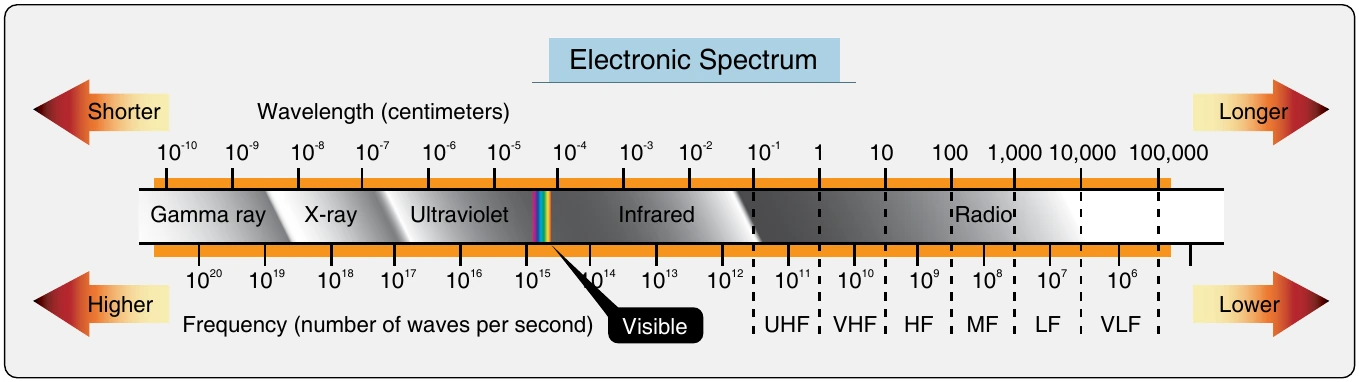
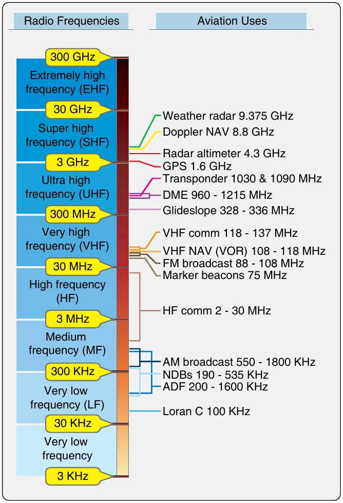
Above HF transmissions, radio waves are known as space waves. They are only capable of line-of-sight transmission and do not refract off of the ionosphere. [Figure 11-78] Most aviation communication and navigational aids operate with space waves. This includes VHF (30 - 300 MHz), UHF (300 MHz - 3 GHz), and super high frequency (SHF) (3 - 30 Ghz) radio waves.
VHF communication radios are the primary communication radios used in aviation. They operate in the frequency range from 118.0 MHz to 136.975 MHz. Seven hundred and twenty separate and distinct channels have been designated in this range with 25 kilohertz spacing between each channel. Further division of the bandwidth is possible, such as in Europe where 8.33 kilohertz separate each VHF communication channel. VHF radios are used for communications between aircraft and air traffic control (ATC), as well as air-to-air communication between aircraft. When using VHF, each party transmits and receives on the same channel. Only one party can transmit at any one time.
Loading Information onto a Radio Wave
The production and broadcast of radio waves does not convey any significant information. The basic radio wave discussed above is known as a carrier wave. To transmit and receive useful information, this wave is altered or modulated by an information signal. The information signal contains the unique voice or data information desired to be conveyed. The modulated carrier wave then carries the information from the transmitting radio to the receiving radio via their respective antennas. Two common methods of modulating carrier waves are amplitude modulation and frequency modulation.
Amplitude Modulation (AM)
A radio wave can be altered to carry useful information by modulating the amplitude of the wave. A DC signal, for example from a microphone, is amplified and then superimposed over the AC carrier wave signal. As the varying DC information signal is amplified, the amplifier output current varies proportionally. The oscillator that creates the carrier wave does so with this varying current. The oscillator frequency output is consistent because it is built into the oscillator circuit. But the amplitude of the oscillator output varies in relation to the fluctuating current input. [Figure 11-79]
When the modulated carrier wave strikes the receiving antenna, voltage is generated that is the same as that which was applied to the transmitter antenna. However, the signal is weaker. It is amplified so that it can be demodulated. Demodulation is the process of removing the original information signal from the carrier wave. Electronic circuits containing capacitors, inductors, diodes, filters, etc., remove all but the desired information signal identical to the original input signal. Then, the information signal is typically amplified again to drive speakers or other output devices. [Figure 11-80]