
Chapter 11
Communication & Navigation
Compass Locators
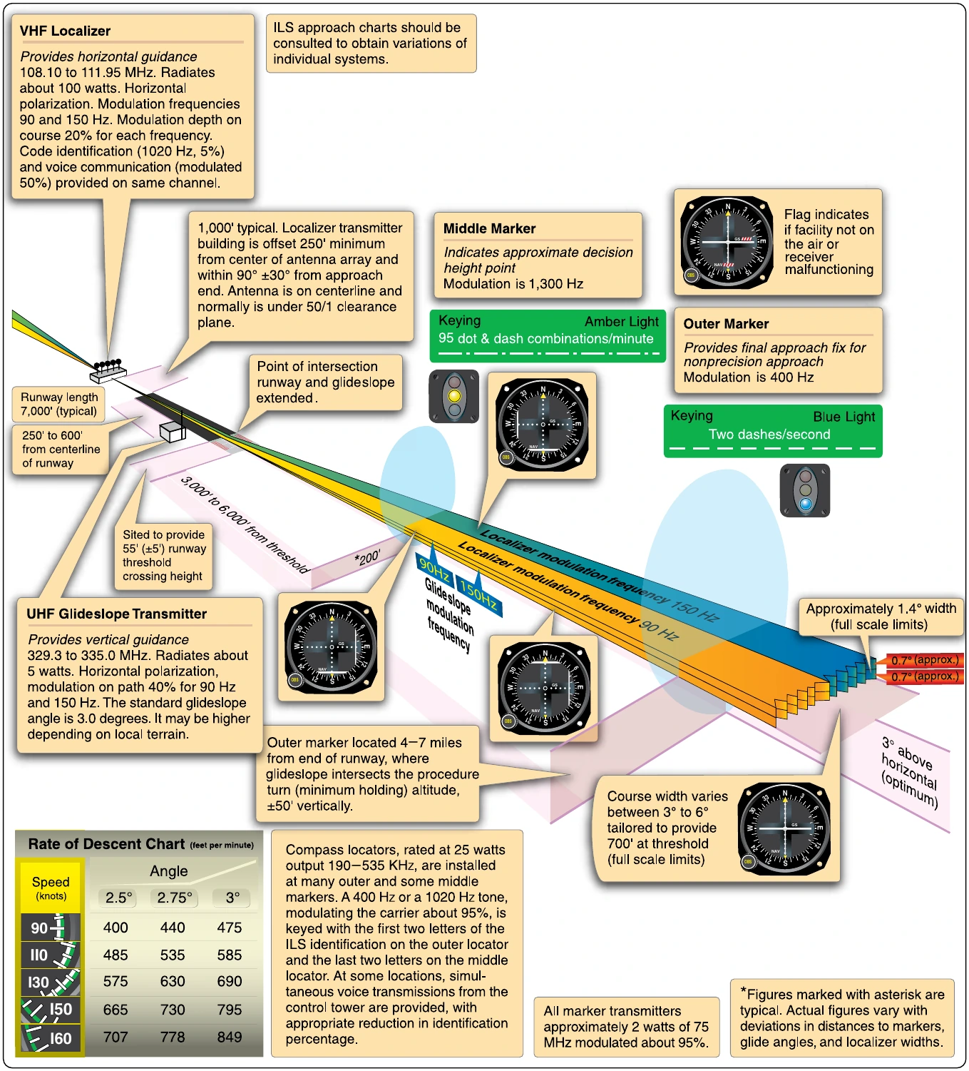
It is imperative that a pilot be able to intercept the ILS to enable its use. A compass locator is a transmitter designed for this purpose. There is typically one located at the outer marker beacon 4–7 miles from the runway threshold.Another may be located at the middle marker beacon about 3,500 feet from the threshold. The outer marker compass locator is a 25 watt NDB with a range of about 15 miles. It transmits omnidirectional LF radio waves (190 Hz to 535 Hz) keyed with the first two letters of the ILS identifier. The ADF receiver is used to intercept the locator so no additional equipment is required. If a middle marker compass locator is in place, it is similar but is identified with the last two letters of the ILS identifier. Once located, the pilot maneuvers the aircraft to fly down the glidepath to the runway.
Marker Beacons
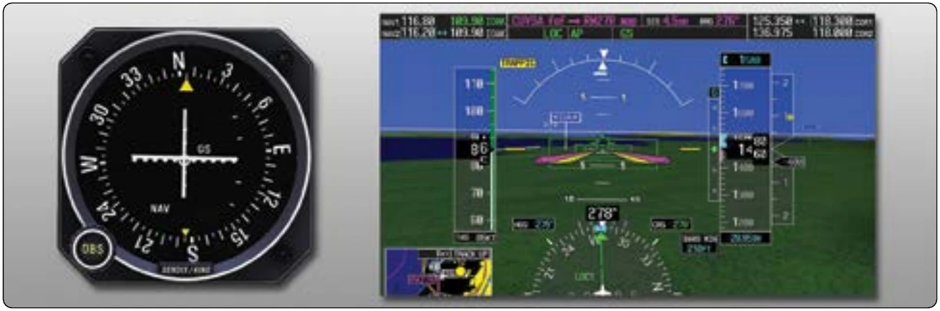
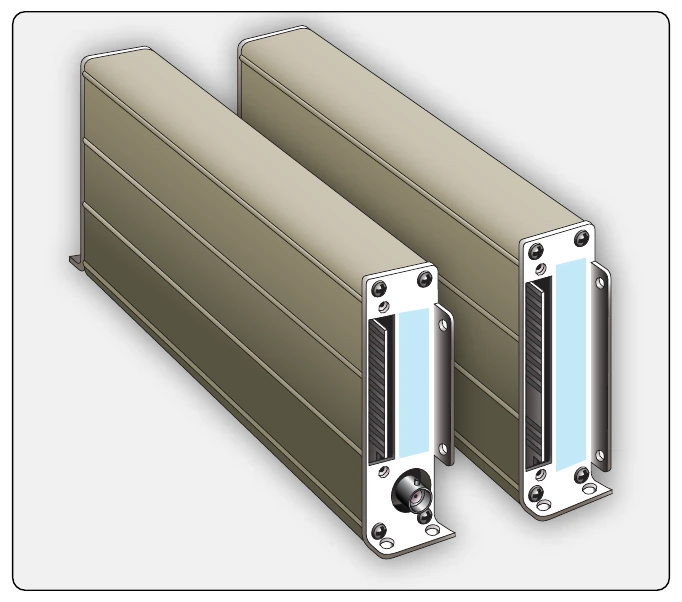
Marker beacons are the final radio transmitters used in the ILS. They transmit signals that indicate the position of the aircraft along the glidepath to the runway. As mentioned, an outer marker beacon transmitter is located 4–7 miles from the threshold. It transmits a 75 MHz carrier wave modulated with a 400 Hz audio tone in a series of dashes. The transmission is very narrow and directed straight up. A marker beacon receiver receives the signal and uses it to light a blue light on the instrument panel. This, plus the oral tone in combination with the localizer and the glideslope indicator, positively locates the aircraft on an approach. [Figure 11-115]
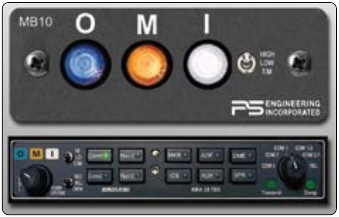
A middle marker beacon is also used. It is located on approach approximately 3,500 feet from the runway. It also transmits at 75 MHz. The middle marker transmission is modulated with a 1300 Hz tone that is a series of dots and dashes so as to not be confused with the all dash tone of the outer marker. When the signal is received, it is used in the receiver to illuminate an amber-colored light on the instrument panel. [Figure 11-116] Some ILS approaches have an inner marker beacon that transmits a signal modulated with 3000 Hz in a series of dots only. It is placed at the land-or-go-around decision point of the approach close to the runway threshold. If present, the signal when received is used to illuminate a white light on the instrument panel. The three marker beacon lights are usually incorporated into the audio panel of a general aviation aircraft or may exist independently on a larger aircraft. Electronic display aircraft usually incorporate marker lights or indicators close to the glideslope display near attitude director indicator. [Figure 11-117]
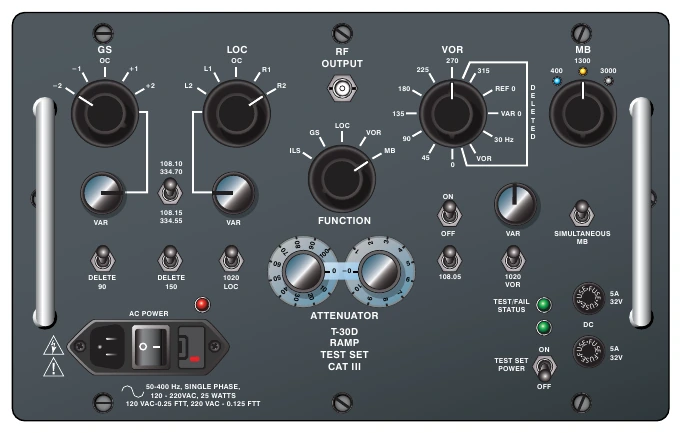
ILS radio components can be tested with an ILS test unit. Localizer, glideslope, and marker beacon signals are generated to ensure proper operation of receivers and correct display on flight deck instruments. [Figure 11-118]
Distance Measuring Equipment (DME)
Many VOR stations are co-located with the military version of the VOR station, which is known as TACAN. When this occurs, the navigation station is known as a VORTAC station. Civilian aircraft make use of one of the TACAN features not originally installed at civilian VOR stations–DME. A DME system calculates the distance from the aircraft to the DME unit at the VORTAC ground station and displays it on the flight deck. It can also display calculated aircraft speed and elapsed time for arrival when the aircraft is traveling to the station.
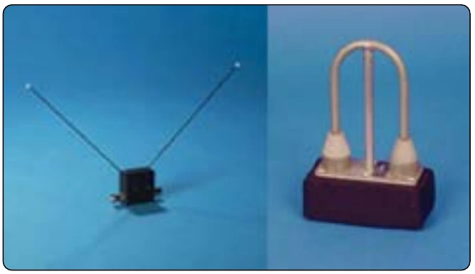
DME ground stations have subsequently been installed at civilian VORs, as well as in conjunction with ILS localizers. These are known as VOR/DME and ILS/DME or LOC/DME. The latter aid in approach to the runway during landings. The DME system consists of an airborne DME transceiver, display, and antenna, as well as the ground based DME unit and its antenna. [Figure 11-119]
The DME is useful because with the bearing (from the VOR) and the distance to a known point (the DME antenna at the VOR), a pilot can positively identify the location of the aircraft. DME operates in the UHF frequency range from 962 MHz to 1213 MHz. A carrier signal transmitted from the aircraft is modulated with a string of integration pulses. The ground unit receives the pulses and returns a signal to the aircraft. The time that transpires for the signal to be sent and returned is calculated and converted into nautical miles for display. Time to station and speed are also calculated and displayed. DME readout can be on a dedicated DME display or it can be part of an EHSI, EADI, EFIS, or on the primary flight display in a glass flight deck. [Figure 11-120]
The DME frequency is paired to the co-located VOR or VORTAC frequency. When the correct frequency is tuned for the VOR signal, the DME is tuned automatically. Tones are broadcast for the VOR station identification and then for the DME. The hold selector on a DME panel keeps the DME tuned in while the VOR selector is tuned to a different VOR. In most cases, the UHF of the DME is transmitted and received via a small blade-type antenna mounted to the underside of the fuselage centerline. [Figure 11-121]
A traditional DME displays the distance from the DME transmitter antenna to the aircraft. This is called the slant distance. It is very accurate. However, since the aircraft is at altitude, the distance to the DME ground antenna from a point directly beneath the aircraft is shorter. Some modern DMEs are equipped to calculate this ground distance and display it. [Figure 11-122]