Chapter 11
Communication & Navigation
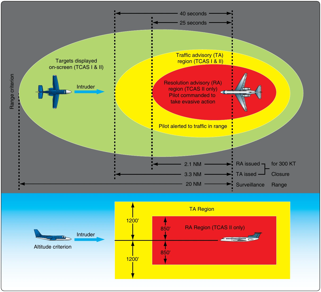
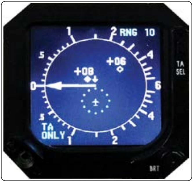
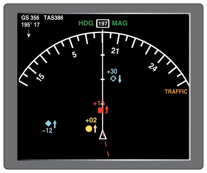
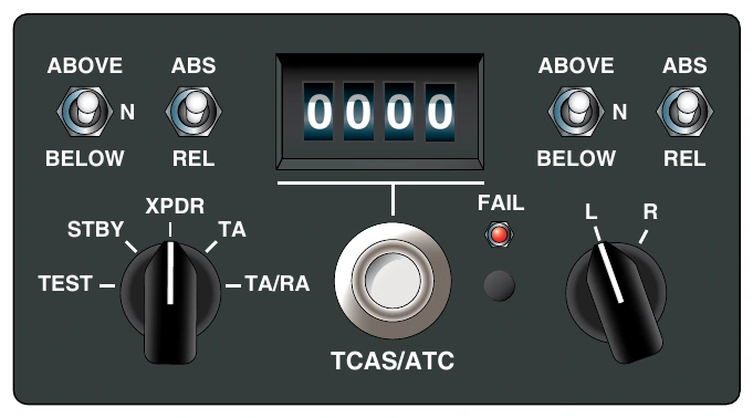
TCAS target aircraft are displayed on a screen on the flight deck. Different colors and shapes are used to depict approaching aircraft depending on the imminent threat level. Since RAs are currently limited to vertical evasive maneuvers, some stand-alone TCAS displays are electronic vertical speed indicators. Most aircraft use some version of an electronic HSI on a navigational screen or page to display TCAS information. [Figure 11-132] A multifunction display may depict TCAS and weather radar information on the same screen. [Figure 11-133] A TCAS control panel [Figure 11-134] and computer are required to work with a compatible transponder and its antenna(s). Interface with EFIS or other previously installed or selected display(s) is also required.
TCAS may be referred to as airborne collision avoidance system (ACAS), which is the international name for the same system. TCAS II with the latest revisions is known as Version
- The accuracy and reliability of this TCAS information is such that pilots are required to follow a TCAS RA over an ATC command.
ADS-B
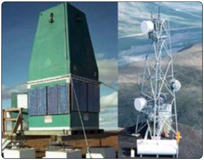
Collision avoidance is a significant part of the FAA’s NextGen plan for transforming the National Airspace System (NAS). Increasing the number of aircraft using the same quantity of airspace and ground facilities requires the implementation of new technologies to maintain a high level of performance and safety. The successful proliferation of global navigation satellite systems (GNSS), such as GPS, has led to the development of a collision avoidance system known as Automatic Dependent Surveillance-Broadcast (ADS-B). ADS-B is an integral part of NextGen program. The implementation of its ground and airborne infrastructure is currently underway. ADS-B is active in parts of the United States and around the world. [Figure 11-135]
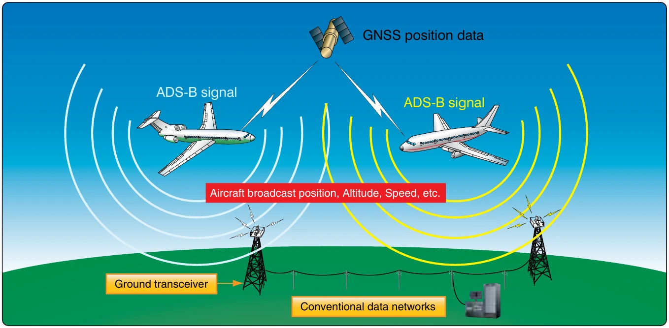
ADS-B is considered in two segments: ADS-B OUT and ADS-B IN. ADS-B OUT combines the positioning information available from a GPS receiver with on-board flight status information, i.e., location including altitude, velocity, and time. It then broadcasts this information to other ADS-B equipped aircraft and ground stations. [Figure 11-136]
Two different frequencies are used to carry these broadcasts with data link capability. The first is an expanded use of the 1090 MHz Mode-S transponder protocol known as 1090 ES. The second, largely being introduced as a new broadband solution for general aviation implementation of ADS-B, is at 978 MHz. A 978 universal access transceiver (UAT) is used to accomplish this. An omni-directional antenna is required in addition to the GPS antenna and receiver. Airborne receivers of an ADS-B use the information to plot the location and movement of the transmitting aircraft on a flight deck display similar to TCAS. [Figure 11-137]
Inexpensive ground stations (compared to radar) are constructed in remote and obstructed areas to proliferate ADS-B. Ground stations share information from airborne ADS-Bs with other ground stations that are part of the air traffic management system (ATMS). Data is transferred with no need for human acknowledgement. Microwave and satellite transmissions are used to link the network.
For traffic separation and control, ADS-B has several advantages over conventional ground-based radar. The first is the entire airspace can be covered with a much lower expense. The aging ATC radar system that is in place is expensive to maintain and replace. Additionally, ADS-B provides more accurate information since the vector state is generated from the aircraft with the help of GPS satellites. Weather is a greatly reduced factor with ADS-B. Ultra-high frequency GPS transmissions are not affected. Increased positioning accuracy allows for higher density traffic flow and landing approaches, an obvious requirement to operate more aircraft in and out of the same number of facilities. The higher degree of control available also enables routing for fewer weather delays and optimal fuel burn rates. Collision avoidance is expanded to include runway incursion from other aircraft and support vehicles on the surface of an airport.
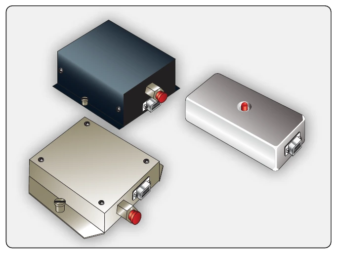
ADS-B IN offers features not available in TCAS. Equipped aircraft are able to receive abundant data to enhance situational awareness. Traffic information services-broadcast (TIS-B) supply traffic information from non-ADS-B aircraft and ADS-B aircraft on a different frequency. Ground radar monitoring of surface targets, and any traffic data in the linked network of ground stations is sent via ADS-B IN to the flight deck. This provides a more complete picture than air-to-air only collision avoidance. Flight information services-broadcast (FIS-B) is also received by ADS-B IN. Weather text and graphics, ATIS information, and NOTAMs are able to be received in aircraft that have 987 UAT capability. [Figure 11-138] ADS-B test units are available for trained maintenance personnel to verify proper operation of ADS-B equipment. This is critical since close tolerance of air traffic separation depends on accurate data from each aircraft and throughout all components of the ADS-B system. [Figure 11-139]
Radio Altimeter
A radio altimeter, or radar altimeter, is used to measure the distance from the aircraft to the terrain directly beneath it. It is used primarily during instrument approach and low level or night flight below 2,500 feet. The radio altimeter supplies the primary altitude information for landing decision height. It incorporates an adjustable altitude bug that creates a visual or aural warning to the pilot when the aircraft reaches that altitude. Typically, the pilot will abort a landing if the decision height is reached and the runway is not visible.
Using a transceiver and a directional antenna, a radio altimeter broadcasts a carrier wave at 4.3 GHz from the aircraft directly toward the ground. The wave is frequency modulated at 50 MHz and travels at a known speed. It strikes surface features and bounces back toward the aircraft where a second antenna receives the return signal. The transceiver processes the signal by measuring the elapsed time the signal traveled and the frequency modulation that occurred. The display indicates height above the terrain also known as above ground level (AGL). [Figure 11-140] A radar altimeter is more accurate and responsive than an air pressure altimeter for AGL information at low altitudes. The transceiver is usually located remotely from the indicator. Multifunctional and glass flight deck displays typically integrate decision height awareness from the radar altimeter as a digital number displayed on the screen with a bug, light, or color change used to indicate when that altitude is reached.